44
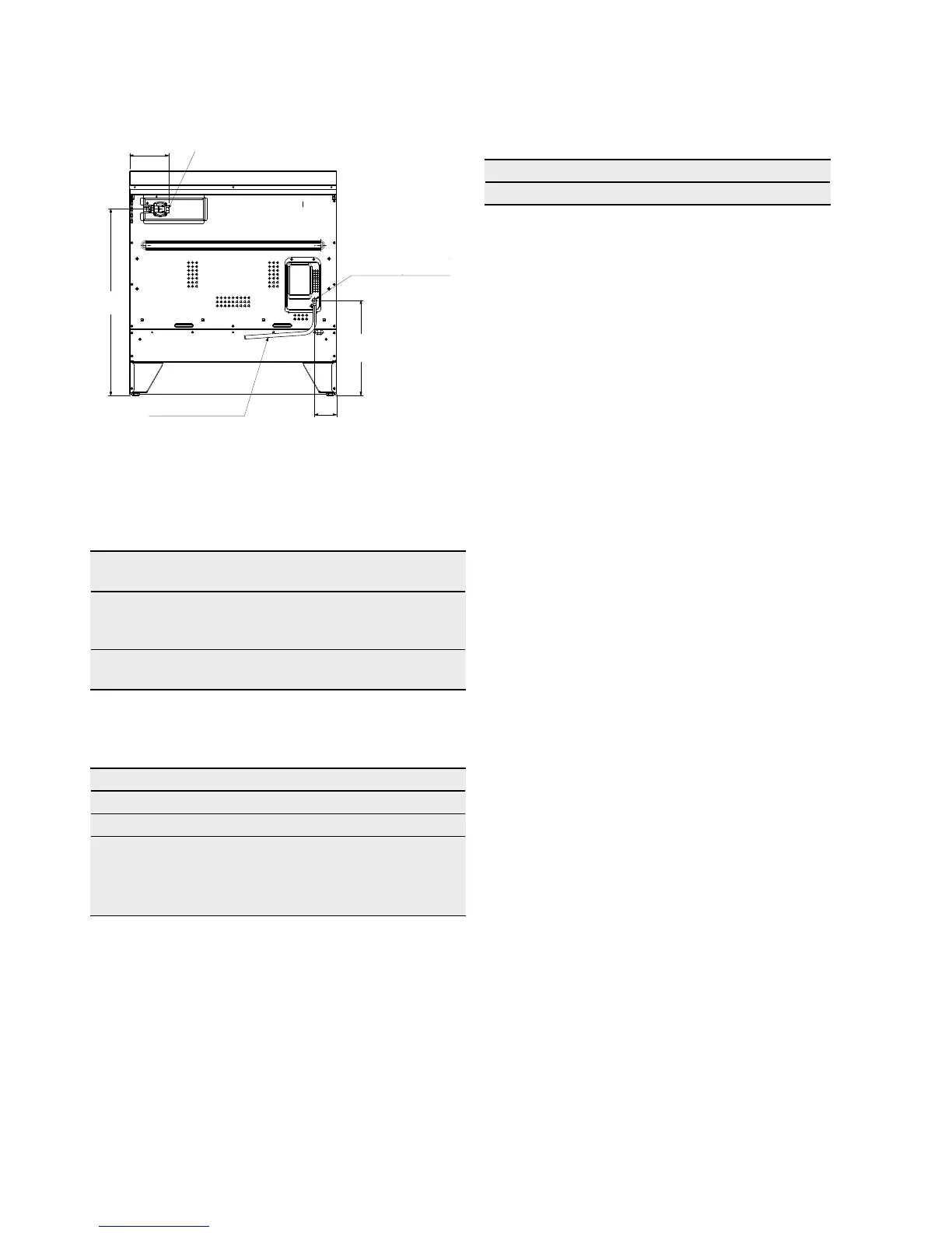
ELECTRICAL & GAS CONNECTION LOCATIONS
The following table shows the supply and operating
pressures for various gases.
Supply pressure at inlet
to appliance regulator (if
fitted)
1.13 ( k Pa )
Minimum
2.75
kPa
Operating pressure at
appliance test point
1.00 (kPa) 2.60 kPa
The following table shows the injector sizes for
each burner.
Low heat burner 1.00mm 0.55mm
Medium heat burner 1.35mm 0.70mm
Intense heat
dual wok burner
0.85mm
(inner)
2 x 1.25mm
(outer)
0.46mm
(inner)
2 x 0.73mm
(outer)
168
95
Electrical connection cable
806
411
Gas connection point to regulator
Models: EFE916BA
Electrical cable
entry point
Models:
EFE916BA,
EFE956BA
To work out a suitable pipe size for connection use the
information in this table:
EFE916BA 66 .1 M J/ h 5 7. 5 M J / h
Information about the length of run, number of elbows,
tees and bends, the available service pressure and the
supply requirements.
NOTE: AS/NZS5601.1 will help you with this matter.
Read these points before connecting to the gas supply:
• Theapplianceispresetfornaturalgasuse.IfLPGis
to be used see Conversion to LPG section.
• Gasinstallationmustbemadeinaccordancewith
AS5601, the local gas fitting regulations, municipal
codes and other statutory regulations.
• Thegasconnectionpointisa½”BSPexternalthread
located at the rear of the appliance as shown.
• Aregulatorissuppliedwhichmustbettedtothe
appliance. Ensure that when fitted the pressure test
point of regulator is accessible.
• Theregulatoristobettedtotheappliance
connection point, then fit hard piping from the
regulator to the consumer hard piping. Ensure the
installation allows the withdrawal of the appliance.
• Theapplianceassuppliedisnotapprovedfor
connection with a flexible hose. However, an approved
flexible hose kit ACC064 is available if the installation
requires use of flexible hose.



 To Next Page