IInnssttaallllaattiioonn IInnffoorrmmaattiioonn
2-4
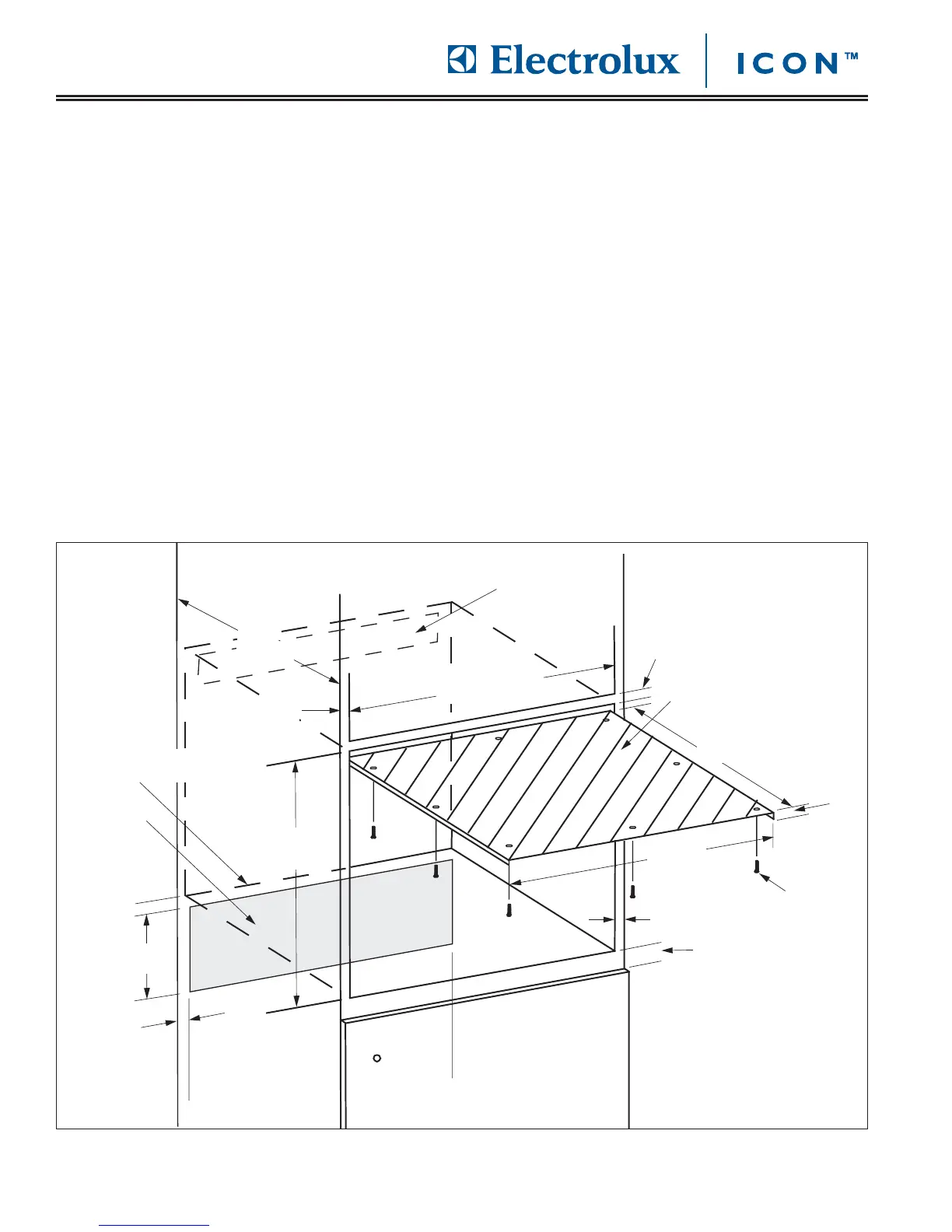
FFiigguurree 22--11.. IInnssttaallllaattiioonn SSiittee RReeqquuiirreemmeennttss
PPllaannnniinngg tthhee LLooccaattiioonn
This section of the manual covers some of the installation issues that a service technician may need to know when
servicing an Electrolux 24” Built-In Coffee Maker. If additional installation information is needed after reviewing this
section of the manual, please refer to the installation guide or contact the Electrolux Customer Service Department.
1. All statutory regulations, local and regional codes and local power supply company connection specifications
must be strictly observed.
2. The supplied power cord is 60” (152.4cm) long, terminated by a three-prong plug. It is located in the lower
right rear corner on the back of the unit. It must be plugged directly into a dedicated, wall-mounted electrical
receptacle.
3. The electrical outlet (and water shut off valve for model E24CM76GSS) should be located in an adjacent cabi-
net. Both must be accessible when the unit is installed.
4. The coffee maker(E24CM76GSS) is supplied with a flexible water hose for connection to a 1/4” threaded water
line connection. See page 2-7 for further information on planning the water line connection.
5. The coffee maker must be installed at a safe distance from other sources of heat, such as home appliances, in
order to avoid an excessive rise in temperature.
6. For ventilation purposes, there must be a slot near the top of the cabinet back. The minimum dimensions are
4” X 12” (10.0 X 30.0cm).
1” Min.
1” Min. (26mm)
Min. Side Walls
Min. Side Walls