© EK Japan 2005
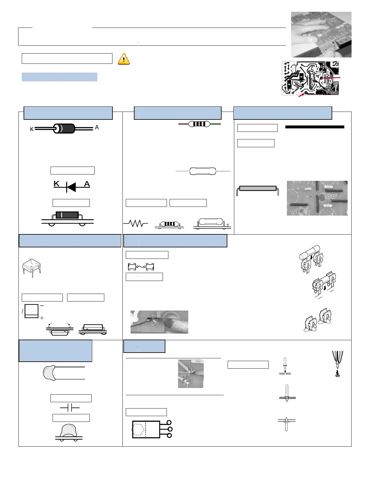
Before you solder, follow the cut line (grooved line) to break the circuit boards TU
There are grooved lines on both sides of the circuit board. Gently use the
2. Circuit Board Assembly
A Circuit Board Assembly
Preparations before you begin
On the soldering side (side with copper foil) of circuit board
Solder plate the 2 holes with copper foils.
/
The line is on the side of K
D1
Marked on PCB
How to install
+,- indication
\
D2, 3
Marked on PCB How to install
C7, 8
220pF (with indication of 221)
Marked on PCB
How to install
Install from solder side (reverse side), total of 12
Install from the side with
Where the fuse holder (metal
fitting) is placed, please
a thick layer of solder plate on the
Diode (direction specific)
(direction specific)
Please pay attention! It is
dangerous if the rectifier is not
installed properly.
Bend the legs on the back of the PCB
to prevent it from falling out when
soldering on the copper foil.
(non direction specific)
Follow the instructions step
have soldered each component.
When soldering, be sure to read “The Key to Soldering.”
info@tubedepot.com
1686 Barcrest Drive, Memphis, TN 38134
Install the metal oxide
film resistor 2-3mm above
the PCB to diffuse heat.
Before you solder, follow the cut line (grooved line) to break the circuit boards TU
-879R A-
E into individual pieces.
There are grooved lines on both sides of the circuit board. Gently use the
edge of a table to break them.
On the soldering side (side with copper foil) of circuit board
A, there are 3 holes with arrows indicated.
(Carbon)
12 330kΩ
(Orange, Orange, Yellow, Gold)
Ω
(Red, Black, Red, Gold)
Ω
(Orange, Orange, Gold, Gold)
Ω
(Brown, Red, Brown, Gold)
Ω
(Red, Red, Green, Gold)
(metal oxide film)
15kΩ(2W)
Ω(3W)
Ω(5W)
on PCB How to install
Marked on
How to install
(1)
(2)
and bend to
the shape in the image below. The
total length of the product should be 35mm. Use
long nose pliers to bend.
(not actual size)
(3)
Solder the jumper wires onto the PCB the same way as the resistors
on PCB
to install
Install from solder side (reverse side), total of 12
Install from the side with
white printing, total of 3
on PCB (FET only)
Where the fuse holder (metal
fitting) is placed, please
pre-apply
a thick layer of solder plate on the
(non-direction
(direction specific)
Follow the instructions step
step. Check off the box after you
have soldered each component.
When soldering, be sure to read “The Key to Soldering.”
and put the legs through the hole
from the solder side.
Bend the legs using long nose pliers to
station it on the PCB. Take the
from the fuse holder and solder the fuse
holders onto the copper foil.
Reinstall the 5X20 GMA
FUSE1 →0.3A FUSE2 →
Caution: 12 pins are installed from the solder side (with copper foil)
and 3 pins are installed from the side with white printing.
Marked on PCB
Insert the pin
perpendicularly into
the hole on the PCB.
solder side (reverse
side) regardless of
which side the pin is
inserted from.
1686 Barcrest Drive, Memphis, TN 38134
3
E into individual pieces.
-coated wire 6-7cm in length.
-coated wire into a plastic tube
the shape in the image below. The
total length of the product should be 35mm. Use
long nose pliers to bend.
Solder the jumper wires onto the PCB the same way as the resistors
(non-direction specific)
Bend the legs using long nose pliers to
fuse
from the fuse holder and solder the fuse
Caution: 12 pins are installed from the solder side (with copper foil)
and 3 pins are installed from the side with white printing.
Put the PCB on a
piece of cardboard
when installing the
pins. Use long nose
pliers to insert the pin.
Do not cut the
protruding base pin
after soldering.
 Loading...