A1015(A733)
C2120(C2001)
K170
B
B
C
E
E
-
74HC04
74HC4017
#
*5 FET
S
S
G
D
D
10m m
2*101)0&
2. Circuit Board Assembly
* The double-sided circuit bard is a through-hole circuit board. be very careful when assembling the parts and make sure
they are in the cirrect marked position. Once a component has been soldered, it is very difficult to remove. If it is
necessary to remove a soldered component, be sure to use a solder wick or a solder sucker.
A. Circuit Board Assembly
* The side with white printing faces upwards. The soldered side faces downwards.
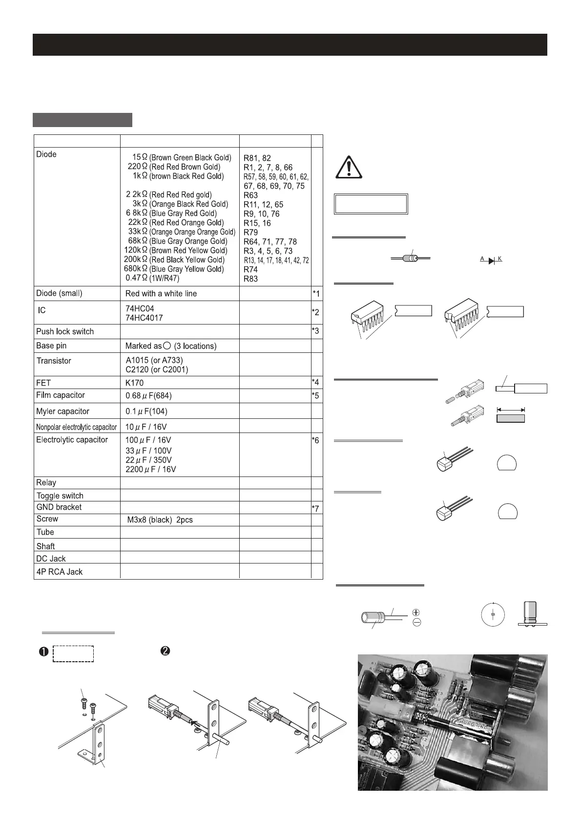
Diode
15 (Brown Green Black Gold) R81, 82
220 (Red Red Brown Gold) R1, 2, 7, 8, 66
1k (brown Black Red Gold) R57, 58, 59, 60, 61, 62,
67, 68, 69, 70, 75
2.2k (Red Red Red gold) R63
3k (Orange Black Red Gold) R11, 12, 65
6.8k (Blue Gray Red Gold) R9, 10, 76
22k (Red Red Orange Gold) R15, 16
33k (Orange Orange Orange Gold) R79
68k (Blue Gray Orange Gold) R64, 71, 77, 78
120k (Brown Red Yel low Gold) R3, 4, 5, 6, 73
200k (Red Black Yel low Gold) R13, 14, 17, 18, 41, 42, 72
680k (Blue Gray Yel low Gold) R74
0.47 (1W/R47) R83
Diode (small) Red with a white line D1-8 *1
IC 74HC04 IC1 *2
74HC4017 IC2
Push lock switch SW1 *3
Base pin Marked as on PCB +7V, GND, B+(HV-IN)
(3 locations)
Transistor A1015 (or A733) TR7 *4
C2120 (or C2001) TR2-6
FET K170 FET1,2 *5
Film capacitor 0.68 F(684) C5,6
Myler capacitor 0.1 F(104) C34, 35, 36
Nonpolar electrolytic capacitor 10 F / 16V C38
Electrolytic capacitor 100 F / 16V C1, 2, 37 *6
33 F / 100V C3, 4, 7, 8
22 F / 350V C33
2200 F / 16V C39
Relay RY1-5
Toggle switch SW2
GND bracket PHONO GND *7
Screw M3x8 (black) 2pcs
Tube
Shaft
DC Jack Jack4
4P RCA Jack Jack 1-3
Main chassis
1pc
Bottom panel
1pc
Transformer
cover
1pc
Front panel
1pc
Volume bracket
1pc
GND bracket
1pc
Knob 2pcs
(screws for knob
included)
Insulator
1pc
Tube
1pc
Vacuum tube 12AU7(5963/6189/ECC82) 3pcs
* Vacuum tubes are made of glass. Please handle with care.
* A metallic black haze visible in the inner wall of the glass indicates
it is a sealed vacuum tube. If this turns white, the vacuum has
leaked and can no longer be used.
* All vacuum tubes have been examined to ensure quality. Some may
have a minor scratch that does not affect the function of the tube.
AC adaptor
(7V 1.8A)
1pc
Vacuum tube socket
MT9P 3pcs
28 parallel jumper cable 1set
Base pin 6pcs
Diode
small 9pcs
large 1R5NU 2pcs
Relay 5pcs
Electrolytic capacitors
100 F / 16V 10pcs
33 F / 100V 6pcs
2200 F / 16V 3pcs
22 F / 350V 3pcs
3.3 F / 350V 1pc
10 F / 50V 2pcs
Potentiometer
(1 nut and washer per channel)
100k B with clicking function
(with indication of 104) 1pc
50k MN with switching function
(with indication of 503) 1pc
Transistor
A1015 (or A733) 1pc
C2120 (or C2001) 5pcs
C3425 1pc
DC Jack 1pc
Toggle switch 1pc
P Push lock switch 1pc
4P RCA pin jack 3pcs
Indication Indication
Resistors (1/4W)
15 (Brown Green Black Gold) 2
220 (Red Red Brown Gold) 11
1k (brown Black Red Gold) 15
2.2k (Red Red Red gold) 5
3k (Orange Black Red Gold) 4
6.8k (Blue Gray Red Gold) 2
15k (Brown Green Orange Gold)
2
22k (Red Red Orange Gold) 2
33k (Orange Orange Orange Gold)
3
68k (Blue Gray Orange Gold) 13
120k (Brown Red Yellow Gold) 10
200k (Red Black Yellow Gold) 12
680k (Blue Gray Yellow Gold) 7
Resistors (1W)
0.47 (with indication of R47) 1
Function label 1pc
Felt 1pc
Transformer 1pc
Hook-up wire
Black 1pc Blue 1pc
Orange 1pc
Screws
M3x8 (black) 21pcs
M3x10 8pcs
Tapping screws
M3x8 3pcs
M3x8 Knurling Head screw 1pc
Hexagon socket head screw
M3x8 4pcs
Screw spacer
M3x15 6pcs
M3x20 2pcs
Shaft 1pc
Film capacitor
0.0022 F (with indication of 222) 4pcs
0.0068 F (with indication of 682) 8pcs
0.68 F (with indication of 684) 4pcs
0.47 F (with indication of 474) 6pcs
Myler capacitor
0.1 F 5pcs
Choke coil
(with indication of 045-100) 1pc
Nonpolar electrolytic capacitor
10 F / 16V 1pc
FET
K170 4pcs
Indication
Indication
Indication
IC
74HC04 1pc
74HC4017 1pc
PQ2CF1 1pc
LED 4pcs
Printed Circuit Board
TU-875R A 1pc
TU-875R B 1pc
TU-875R C.D 1pc
1. Part List * Please check off the box in front of each item to ensure they have been included in the kit.
* Warning! Electrolytic capacitor has a negative
end and positive end. It is dangerous if the
electrolytic capacitor is not installed properly.
Parts with polarity
*1 Diode (small)
The line is on the side of K.
*2 IC
Match the mark
Match the mark
*3 Push lock switch
Switch side
Set it in the direction indicated
on the PCB and solder. Cut the
tube to 10mm and set to the
switch.
*4 Transistor
Indication
Indication
* Try to have the toggle switch /DC Jack / 4 pin RCA Jack
to sit straight when soldering.
*6 Electrolytic capacitor
The side with longer lead is positive.
The side with shorter lead is negative.
* Place the capacitor vertically.
*7 GND bracket
Fix the bracket with black M3x8
screws on the marked position.
M3x8 (black)
Insert the shaft into the push lock switch.
GND brakcet
Shaft
Part List Value Part Number
15 (Brown Green Black Gold)
220 (Red Red Brown Gold)
1k (brown Black Red Gold)
2.2k (Red Red Red gold)
3k (Orange Black Red Gold)
6.8k (Blue Gray Red Gold)
22k (Red Red Orange Gold)
33k (Orange Orange Orange Gold)
68k (Blue Gray Orange Gold)
120k (Brown Red Yel low Gold)
200k (Red Black Yel low Gold)
680k (Blue Gray Yel low Gold)
0.47 (1W/R47)
 Loading...