ELEKTROGAS – TECHNICAL MANUAL
8-13
Ordering
information
Tab.4
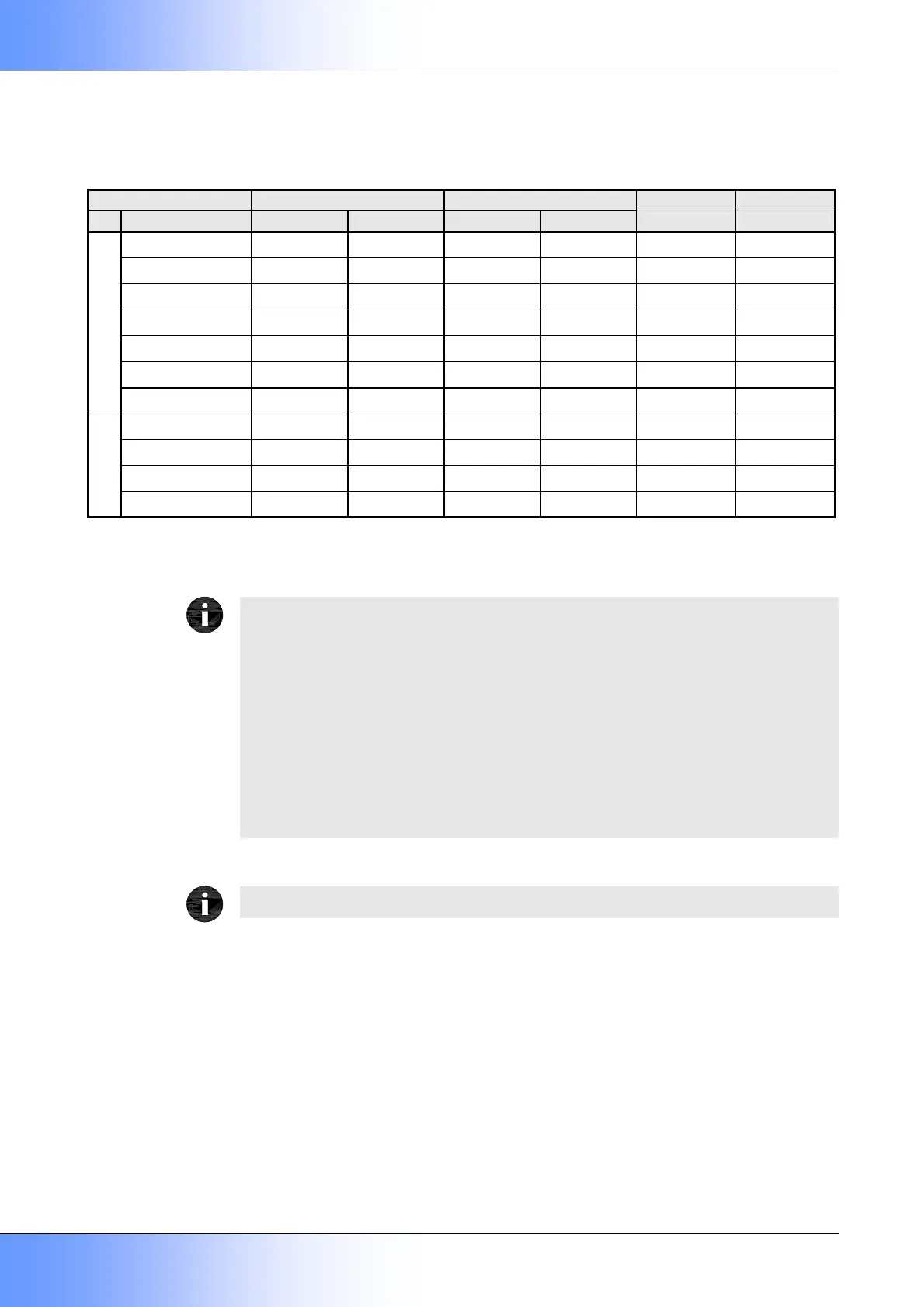
Material and Connections 230V 110V 24V
AlSi 200 mbar 360 mbar 200 mbar 360 mbar 200 mbar
Rp 3/8 VML0 VML0.B VML02.C
Rp 1/2 VML1 VML1.B VML12.C
Rp 3/4 VML2 VML2.B VML22.C
Rp 1 VML3 VML3.B VML32.C
Rp 11/4 VML35 VML35.B VML352.C
Rp 11/2 VML4 VML4.B VML42.C
Threaded
Rp 2 VML6 VML6.B VML62.C
DN 40
1
VML4F VML4F.B VML42F.C
DN 50
1
VML6F VML6F.B VML62F.C
DN 65 VML72 VML7 VML72.B VML7.B
Flanged
DN 80 VML82 VML8 VML82.B VML8.B
(
1
) Optional kit
The versions with inlet pressure p
1
≤ 200 mbar (20 kPa) may be order inserting the digit “2” in
to the designation.
Different voltage than 230V may be order adding to the standard designation the additional
code as shown above.
The special version suitable for aggressive gases may be order adding to the standard
designation the additional code “K”.
Other optionals (i.e. standard plug, IP65 version) must be order with their ordering code.
Examples:
VML72.B for a valve with DN65 flanged connections, 110VAC, 200 mbar
VML3.K for a valve with Rp1 threaded connections, 230VAC, 360 mbar, suitable for
aggressive gases
Manufacturer reserves the right to update or make technical changes without prior notice.
 Loading...