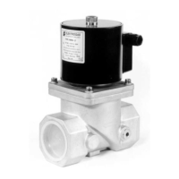
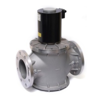
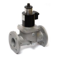
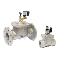
VMR FAST SAFETY SOLENOID VALVE
CLASS A - GROUP 2 (EN 161)
The VMR type valve is a fast opening solenoid valve that is normally closed. When not energized the spring works on
the seat keeping the gas passage closed. When the coil is powered the valve opens. When power is turn off the
valve rapidly shuts.
This type of device is suitable for gas and air blocking and adjusting controls in atmospheric burners or fan-assisted
burners, in industrial ovens and in all gas equipments which use gas solenoid valves (qualified for continuous service
- 100% ED).
1- INSTALLATION (Qualified technicians only and in compliance with the rules in force)
Shut off the gas supply and electrical power before servicing any part of the system.
Check correspondence of flow direction with arrow printed on valve body, check correct alignment of connecting
pipes and allow enough space from the walls to allow free air circulation. Avoid overtightening and use proper tools
only. We recommend installing a filter upstream of each installation (d< 1mm). Valve may be mounted with coil in
horizontal or vertical position. Coil may be oriented 360 degrees in any direction. Install in an area that is protected
from rain and water splashes or drops.
2- ELECTRICAL CONNECTION (IEC 730-1)
Remove protection cover and connect power cables to rectifier circuit terminal board. Respect printed symbols. When
reassemble use cable gland properly. If cables should pass through originally closed opening, use a suitable plug to
close the other opening.
Perform leak and functional tests after mounting.
3- FLOW ADJUSTMENT
Capacity may be adjusted from 0 cubic meters/h to the maximum marked on the plate (excepting brass models and
4"-5"-6" model). Remove coil fastener cap, turn adjustment screw under locking dowel. Make sure that capacity
adjustments are made while burner is in operation, and when adjustment is completed screw back locking dowel.
Adjustments below 40% capacity are unadvisable since they may cause turbulence.
Coil can be hot, avoid to touch it.
4- CLEANING AND MAINTENANCE (Once per year)
Dust and any foreign bodies may be easily removed from the filter or the gas passage zone. After shutting off
upstream gas and electric current, remove the coil and unscrew the screws fixing the upper flange to the valve body.
During this operation care should be taken not to cause damage to the sealing lip and the sliding rings.
Recommended service life: 10 years (see date of manufacture on the label: wwyy).
5- PRODUCT DISPOSAL
The device contains electronic components and cannot therefore be disposed of as normal household waste.
For the disposal procedure, please refer to the local rules in force for special waste.
6- TECHNICAL SPECIFICATIONS
Connections : gas threaded ISO 7-1 from Rp1/4 to Rp2½
: flanged ISO 7005-PN16 from DN40 to DN150
Voltage rating : 230VAC, 110VAC, 24V AC/DC, 12V AC/DC
Voltage tolerance : -15% / +10%
Ambient temperature : -15°C / +60°C
Max. Operating pressure (Pmax) : see product label
Body test pressure : 1,5·Pmax
Opening time : < 1 second
Closing time : < 1 second
Cable glands (EN 50262) : M20x1,5 for cable Ø8/10 (PG9 for standard plug cable Ø6/8)
Pressure ports : G1/4 on two sides (except brass models)
Limit switch facilities : on demand
Strainer : 600 µm (except brass models)
Gas type (EN 437) : air and non-aggressive gases 1, 2 and 3 (gaseous state only)
(special version for aggressive gases or COG - *compatibility of gas
contents and valve materials to be checked before installation)
ATEX INSTALLATION: Special conditions for safe use (X)
1) Ambient temperature -15°C/+40°C; 2) Low mechanical danger; 3) Clean with a mist cloth; 4) Do not disconnect the
plug when energized; 5) Ensure an external grounding of the valve housing.
Elektrogas reserves the right to update or make technical changes without prior notice.
 Loading...