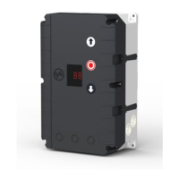
Do you have a question about the Elektromaten TS 961 and is the answer not in the manual?
| Brand | Elektromaten |
|---|---|
| Model | TS 961 |
| Category | Control Panel |
| Language | English |
General safety guidelines for the control system installation and operation.
Overview of European and VDE regulations to be observed during installation and operation.
Explains the meaning of individual warning symbols used in the manual.
Provides general safety advice for installation, operation, and conjunction with other devices.
Guidance on installing the enclosure and wiring the drive to the control panel.
Instructions for connecting limit switches, covering different versions.
Information on connecting mains supply and checking phase rotation.
Steps for adjusting limit switches for optimal door operation.
Guidance on safety devices and programming door functions.
Visual overview of electrical connections for the control panel and accessories.
Recommendations for mounting the enclosure, ensuring flatness and vertical orientation.
Details on connecting the drive and control panel using plug-in cables.
Pin assignments and wire numbers for motor and limit switch connections.
Wiring diagram and instructions for plug-in limit switch systems.
Wiring diagram for terminal version limit switches up to 1997.
Wiring diagram for systems using single-limit switches.
Diagrams illustrating different mains supply terminal configurations for 400V and 230V.
Diagrams for connecting three-phase and single-phase motors in various configurations.
Procedure to check and correct motor phase rotation for correct door operation.
Steps to move the door to the open position and set the final open limit switch.
Steps to move the door to the close position and set the final close limit switch.
Overview of terminal connections (X1-X9) and key components on the control panel.
Diagrams illustrating wiring for normally closed, normally open, and optical safety edges.
Wiring diagrams for emergency stop, key switches, push buttons, and photo-beams.
Wiring for warning lights, aux. contacts, and main supply connections.
Procedure to access the control programming mode using the selector switch.
Steps for choosing programs, adjusting functions, and memorizing settings.
Method to exit the programming mode after making adjustments.
Options for setting the door operating mode (e.g., Dead man, Self-hold).
Configuration options for safety edge, automatic closing, relay, and step-by-step functions.
Settings for the maintenance cycle counter and system reset procedures.
How to check cycle counters, last faults, and program versions.
Details on three types of safety edges: 1K2, 8K2, and Optical.
Instructions for mounting the spiral cable and connecting the safety edge system.
Procedure for setting the pre-limit switch S5 to prevent unintended re-opening.
Detailed explanation of the 1K2 safety edge system, including pressure-wave switch function.
Description of the 8K2 safety edge system with normally open contact.
Explanation of the optical safety edge system principle.
Table outlining reactions for active and de-activated safety edges.
Information on connecting an emergency stop button or other safety devices.
Description of key switches for interrupting automatic closing and intermediate stops.
Details on internal/external push buttons and runtime monitoring settings.
Explanation of automatic closing timers and interruption by photo-beam.
How the photo-beam functions and its reactions to interruptions in different door states.
Operation sequence for ceiling pull switches and radio controls.
Activation and deactivation of intermediate stop using a key switch.
Functions of the potential free changeover contact, including impulse and continuous signals.
Setup and function of the free adjustable maintenance cycle counter.
Information on the control panel's short circuit and overload monitoring for external devices.
Displays fault codes (Fxx) with descriptions and measures to solve the problems.
Further fault codes (F25-F34) and their corresponding troubleshooting measures.
Internal system faults (ROM, RAM, control) and time overrun issues.
Status codes (Exx) indicating open, stop, or close commands being issued.
Detailed technical specifications including dimensions, supply, load, inputs, and temperature.
Graph illustrating the relationship between power and expected lifetime cycles for ELEKTROMATEN®.
Declaration of conformance with EC directives and list of applied standards.