Do you have a question about the Elenco Electronics GFG-8016D and is the answer not in the manual?
Overview of the Digital Function Generator's capabilities, frequency range, and counter features.
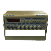
Details all controls and indicators located on the front panel for operating the generator.
Describes the power cord receptacle on the rear panel and main P.C. board layout.
Explains the internal working principle of the function generator using current sources and timing capacitors.
Covers frequency range, accuracy, output amplitude, sine wave distortion, and square wave rise time.
Details V.C.F. input, amplitude attenuation, DC offset range, and CMOS level control.
Includes power source, accessories, dimensions, weight, and frequency counter specifications.
Covers unpacking, inspection, AC power requirements, and fuse replacement.
Details the POWER SWITCH, RANGE, FUNCTION, and MULTIPLIER controls for basic operation.
Explains how the DUTY potentiometer controls time symmetry and the INVERT switch inverts it.
Describes the DC OFFSET control for adjusting waveform DC level and the NOTE about amplitude/offset limits.
Details AMPLITUDE, OUTPUT, VCF INPUT, PULSE OUTPUT, CMOS LEVEL CONTROL, and PULSE OUTPUT SWITCH.
Covers frequency counter selectors, display, input connector, and indicator lamps.
Describes the Hz KHz LED, GATE LED, and OVER LED indicators.
Describes the operation of the DIGITAL FUNCTION GENERATOR in detail and refers to the Block Diagram.
Covers the Summing Amplifier, Inverter, and Current Sources essential for waveform generation.
Explains DUTY CONTROL, INVERT SWITCH, and PULSE OUTPUT functionality.
Details BUFFER, LEVEL DETECTOR, and CURRENT SOURCE DIODE SWITCH stages.
Describes TTL GATE, SINE AMPLIFIER, and OUTPUT AMPLIFIER for signal processing.
Explains the summing amplifier's role in frequency sweeping via MULTIPLIER and VCF input.
Explains the inverter and the positive/negative current sources for timing capacitor control.
Schematic for the main generator section, including summing amplifier, current sources, and range switching.
Schematic for sine amplifier, output amplifier, and related components.
Schematic for the power supply unit, including voltage regulation.
Schematic for the frequency counter display and control logic.
| Brand | Elenco Electronics |
|---|---|
| Model | GFG-8016D |
| Category | Inverter |
| Language | English |