After the venetian blind motor has been installed, attach these
instructions to the cable for the use of the electrician.
Mounting instructions
Mounting of the safety cut-out „right hand installation“
Remove label on the bottom side of the limit switch housing and
insert the safety cut-out with orange or black cap in the openings
and engage it in such a way that the orange or black pressure pin
points towards the side of the orange adjustment push-button UP.
If the supplied safety cut-out cannot be used, e.g. due to lack of
space, then the label must not be removed since it protects the
inside of the limit switch against dirt.
If the safety cut-out is not long
enough, it can be extended by
10 mm at a time with the safety
cut-out extension (article
number 16 101.4501).
(Maximum of 3 safety cut-out
extensions can be plugged on).
Insert the blade of a small flat
screwdriver into one of the
grooves on the orange cover and by pressing the blade towards
the middle of the safety cut-out, lever off the cover. Clip on the
extension and then clip on the cover again.
Mounting of the QuickSnap coupling for JA
1. Apply coupling at an angle whilst observing the position of the
coupling with respect to the shaft: The stop spring should slide
on the upper surface of the hexagonal shaft.
2. Push coupling a little further until the spring audibly latches
into the groove. (Click).
3. If the groove is covered by a bearing or lockwasher, the
hexagonal shaft can be correspondingly pushed back until the
coupling spring latches into place.
4. By pulling it by jerks check that the coupling is securely seated.
Dismantling of the QuickSnap coupling for JA
Do not forcibly remove the coupling.
1. Lift up the motor coupling retaining spring on the shaft with a
small screwdriver.
2. Pull off the coupling.
Installation in headpiece
Installation instructions:
• Install drive without restraint, in
correct position (safety cut-out
showing downwards), and properly
aligned with the shafts in the
venetian blind head.
• Impacts (e.g. hammer blows) are not
permitted on drive, shaft or coupling.
• The axle height of the drive is
27.5 mm. See JA accessories for
dampers for different bearing blocks
axle heights.
• Make sure that the shaft is not radially loaded.
• Make electrical connection with installation
cable (article number 23 246.0001) and check
the turning direction of the drive shaft
according to the direction advice on the front
of the limit switch housing. Travel to the lower
end position again with the DOWN pushbutton.
• Couple drive to shaft. Note the correct setting
for the slats.
Left-hand installation is not possible with JAR drives.
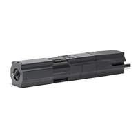
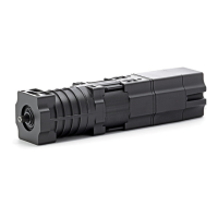
JAR Venetian Blind Motors
removable label
damper
countersunk bolt
withcross recess
H no. 3
22
32
Setting instructions:
Venetian blind drives are supplied
from the factory already set to the
lower end position “Ab1” (Down1).
Connect installation cable to
venetian blind drive
.
Setting the upper end position::
Setting of the upper end point is
only necessary if the end position is
located ahead of switch-off by the
safety cut-out. Otherwise the
venetian blind is only switched off
by the safety cut-out.
• Move venetian blind upwards with
the corresponding push button.
• Simultaneously press the
orange adjustment button
and hold it down for at
least 5 seconds. (Adjustment
button remains latched.)
Adjustment push
button (white)
DOWN
Adjustment push
button (white)
DOWN
Adjustment push
button (white)
DOWN1
Safety
cut-out
Button 1
Button 2
Button 3
Working setting
Advice
This must have taken place at latest 0.5 m before reaching the
end position. After pressing the adjustment button it must stay
latched in.
• With the help of the installation cable travel directly to the upper
end position (fine adjustment by means of inching operation
with the installation cable).
• By changing the direction of travel the adjustment button is
automatically unlatched and the upper end position is then set.
Setting the lower end position:
It is not normally necessary to set the lower end position since the
ventian blind drives are set to the lower end position in the factory.
If it is necessary however the setting takes place in the same way as
for the upper end position.
• Move venetian blind downwards with the corresponding push
button.
• Not less than 0.5 m before reaching the lower setting press in the
two white adjustment buttons AB1 and AB2 (Down1 and
Down2)at the same time and keep them pressed for at least 5
seconds.
Advice:
This must have taken place at latest 0.5 m before reaching the
end
position. After pressing the adjustment button it must stay
latched in.
• With the help of the installation cable travel directly to the lower
end position (fine adjustment by means of inching operation
with the installation cable).
•
By changing the direction of travel the adjustment button is
automatically unlatched and the lower end position is then set.