EasyManua.ls Logo

Elesta DOMOTESTA RDO353A series User Manual

Elesta DOMOTESTA RDO353A series
52 pages
To Next Page IconTo Next Page
Page #1 background imageLoading...
Page #1 background image
User manual: RDO3x3A
162515v44/11.10
Specifications are subject to change
1
User manual
DOMOTESTA
- RDO353A... V4.40
- RDO383A... V4.40
Weather- or room temperature-compensated
heating controller
Question and Answer IconNeed help?

Do you have a question about the Elesta DOMOTESTA RDO353A series and is the answer not in the manual?

Elesta DOMOTESTA RDO353A series Specifications

General IconGeneral
Control ModeON/OFF, PID
Input TypePt100
Output TypeRelay, SSR
Supply Voltage24 VAC/DC
DisplayLED
Operating Temperature0°C to +50°C
Protection ClassIP20

Summary

User Manual

1 General

2 Safety regulations

Proper and safe usage guidelines

Outlines correct application and compliance standards.

3 Operation

3.1 Operating elements

3.2 Display

LCD display indicators and symbols

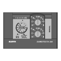
Explains the meaning of icons and readings.

3.2.3 Indication of errors

Error numbers and description

3.3 Operation level 1: Simple operation settings

3.3.3 Temperature setpoint adjustment

3.4 Operation level II: Advanced operation settings

3.4.1 Operation navigation and selection

Explains how to navigate and select functions.

3.4.2 Setting time and date correctly

Details accurate time and date configuration.

3.4.3 Holiday program setup

3.4.4 Set time switch program

3.4.5 Adjust temperature setpoints

3.4.6 Correct room temperature deviation

3.4.7 Display service data

Error list

4 Installation

4.1 Controller

General information about the controller unit.

4.1.2 Mounting instructions

Details how to install the controller.

4.2 Sensors

4.2.1 Remote control units and sensors

Details wired remote control units and sensors.

4.2.3 Passive temperature sensors

4.3 Accessories

Bus interface types

Describes different bus interface options.

Bus interface specifications

5 Terminal assignment

5.1 Terminal designation

A: 230VAC: Inputs and outputs

Specific terminal assignments for mains voltage.

B: Low voltage: Inputs and outputs

Specific terminal assignments for low voltage.

5.2 Controller RDO353A wiring

5.3 Controller RDO383A wiring

5.4 Heating circuit module RZM510A004

5.5 Boiler cascade module RZM530A004

5.6 DHW module RZM515A004

5.7 Address and parameter setting

Boiler cascade and gas boiler controller configuration

Warning: Address setting for modules

6 Checklists

6.1 Initial start up checklist

Checklist for the first-time setup.

6.2 Troubleshooting checklist

Guide for diagnosing and resolving issues.

Emergency operation general procedures

Emergency operation for boiler cascades

Emergency operation for district heating

7 Expert level I: Parameter setting

Configuration of energy production/hydraulics

Covers parameters related to energy sources and hydraulics.

8 Expert level II: System test

Outputs allocated to heat generator

Outputs allocated to DHW

9 Abbreviations

10 Protocol: Setpoints, time switch program, ...

DHW 1 in RDO

DHW circuit 2

DHW circuit 3

DHW circuit 4

Heating circuit 1

Heating circuit 2

Heating circuit 3

Heating circuit 4

Heating circuit 5

Heating circuit 6

Heating circuit 7