EM38A / EM38A-R / EM38A-X User’s Manual Page 2 of 8
Parallel Trigger Modes
Parallel Trigger Mode defines how the playback is to be triggered
via the trigger inputs. All inputs are internally pulled up and, if left
unconnected, have a voltage of 3.3V (logic “1”). 5V signal is toler-
ated and also seen as logic “1”. Logic “0” is ground.
Direct Trigger (default)
In this mode each input directly triggers a corresponding file: T1 =
File 001, T2 = File 002, ......, T8 = File 008.
A trigger is valid when the input is shorted to the ground for at least
50 ms. The Direct Trigger is prioritized from T1 (the highest) to T8
(the lowest). However, it does not mean a higher priority input can
interrupt a lower one. It only means that if multiple triggers are
applied at the same time, the highest priority wins.
Binary Trigger
Use the Binary Trigger to trigger up to 128 different files ranging
from 001 to 128. The Binary Trigger is often preferred when the
system is controlled by an external controller because it requires
less I/O ports in most cases.
To trigger a particular file, the first step is to signal the file number
on T1 (LSB) ~ T7 (MSB). The signal must be in the binary format
with +5V being logic “1”, and 0V (the ground) being logic “0”. For
example, to signal File 007 (binary code “0000111”), T1 ~ T3 should
be at +5V, and T4 ~ T7 should be at 0V. Note that, as a special
case, the binary code for File 128 is “0000000”.
The second and the last step is to short T8 to the ground for at
least 50 ms while maintaining the signal on T1 ~ T7. Afterwards,
signals on T1 ~ T7 don’t matter any more.
Sequential Trigger
Use the Sequential Trigger to sequentially trigger up to 99 different
files per input as described below. However, the total number of
files cannot exceed 511 unless the memory card is formatted with
the FAT32 file system.
T1 triggers File 001 ~ 099
T2 triggers File 201 ~ 299
......
T8 triggers File 801 ~ 899
Each trigger on the same input activates the next file in the se-
quence. The sequence automatically restarts when either the end
of the sequence is reached or there is a break in the sequence.
For example, if there are only three files on the flash card: 001,
002, and 004, the system will only sequence from 001 to 002. File
004 will never be played because File 003 is missing.
The Sequential Trigger is prioritized from T1 (the highest) to T8
(the lowest). However, it does not mean a higher priority input can
interrupt a lower one. It only means that if multiple triggers are
applied at the same time, the highest priority wins.
Round-Robin Trigger
This mode is very similar to the Direct Trigger mode except that the
inputs are not prioritized. So if multiple inputs are tied to ground
then their files will be played one after another, instead of just the
highest priority one. Round-Robin mode can only be used in con-
junction with Non-interruptible Playback and Script Playback.
Parallel Playback Modes
Non-interruptible Playback (default)
The file is played once per trigger. The playback is not interruptible
except by the system reset. Looping is possible by applying a con-
stant trigger on the input.
Interruptible Playback
The file is played once per trigger if not interrupted. Any input but
itself can interrupt the playback. Looping is possible by applying a
constant trigger on the input.
Holdable Playback
The file is played for as long as the input is triggered, looping if
necessary. It is not interruptible except by the system reset.
Script Playback
Please see the Script Playback Mode section for descriptions.
Parallel Trigger Polarity
Close Contact
Input is continuously triggered when it’s at 0V (ground).
Open Contact
Input is continuously triggered when it’s left open or at 3.3V/5V.
Make Contact
Input is triggered one time as it goes from 3.3V/5V to 0V.
Break Contact
Input is triggered one time as it goes from 0V to 3.3V/5V.
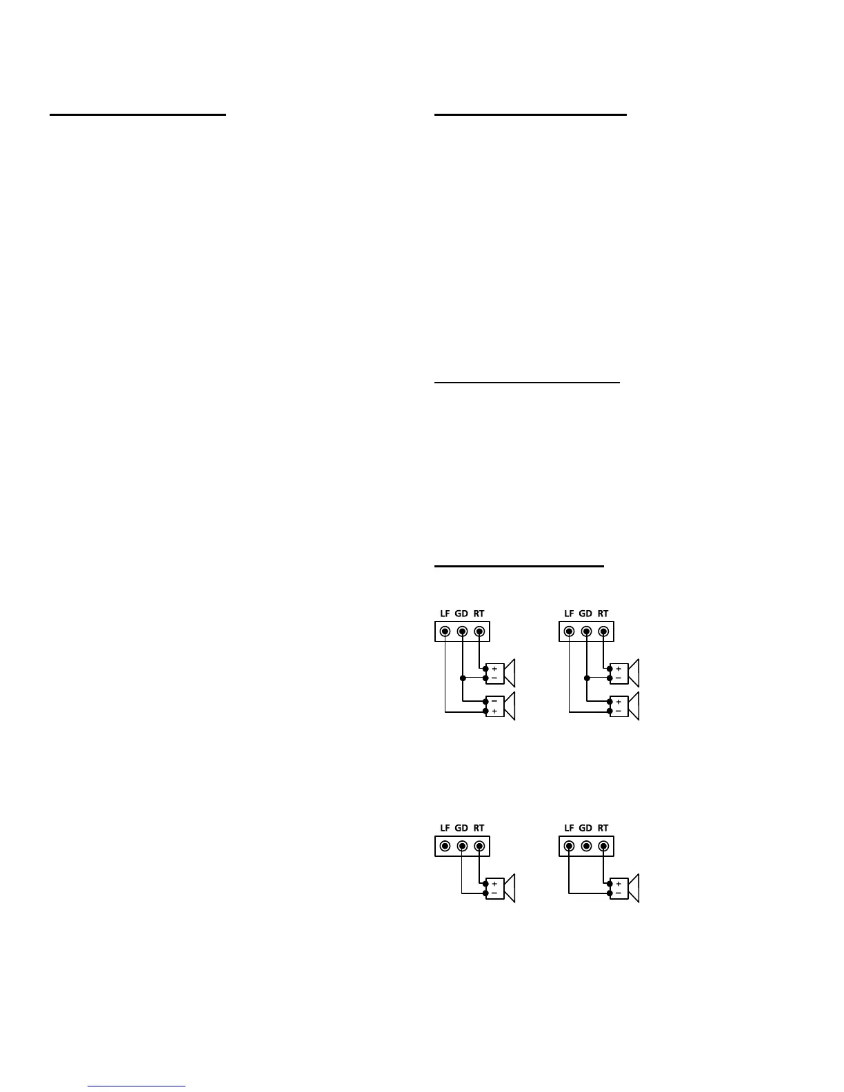
Speaker Connections
Regular Stereo Virtual Surround Stereo
The left channel signal is internally inverted and that’s why the left
speaker has an inverted polarity for regular stereo output. If the left
speaker is not inverted then the output is virtual surround stereo.
Regular Mono BTL Mono (4X Output Power)
Since BTL mono provides four times the output power of regular
mono at the same supply voltage, it is often used to boost the output
power when the supply voltage is low. However, the speaker
impedence should not be lower than 8 Ohms to avoid overloading
the power amp.
 Loading...