The Eletta D-series Flow Monitor is an instrument designed for measuring and controlling the flow of liquids and gases in various pipe systems. It operates on the differential pressure principle, offering a robust and dependable solution for flow monitoring.
Function Description
The D-series Flow Monitor measures flow by creating a differential pressure across an interchangeable orifice plate within the pipe section. This pressure difference is sensed by a mechanical mechanism in the Control Unit's diaphragm housing, which then translates the movement into a flow rate value. The instrument provides a linear flow output, which can be transmitted as a 4-20 mA signal, HART protocol, pulse, or 200-1000 Hz frequency.
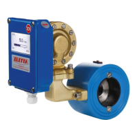
The instrument consists of two main parts: the Pipe Section and the Control Unit. The Pipe Section is installed in-line with the process pipe, while the Control Unit can be mounted directly on top of the Pipe Section or remotely, for instance, when measuring hot media or in cases of high vibration.
The D-series offers enhanced accuracy compared to Eletta's V and S-series due to fewer moving parts and less mechanical linkage within the Control Unit. Instead of micro switches, it utilizes a linear potentiometer to provide information to the circuit board.
Important Technical Specifications
Flow Range:
- Liquids: 0.4-25,000 l/min, depending on pipe size. Standard flow ranges for water and oil are provided in the manual.
- Gases: Calculated according to application.
Flow Measuring Range (Turn Down):
- D2-model: TD of 1:2 (50-100% Flow Range)
- D5-model: TD of 1:5 (20-100% Flow Range)
Accuracy:
- ±2% F.S. (Full scale) under ideal conditions (straight runs, temperature, pressure, viscosity, and density). For optimal accuracy, the normal process flow should be in the middle of the Monitor's flow range.
Pressure:
- Pressure class: PN16 / ANSI 150 lbs
- Max static pressure: 16 bar (232 PSI)
- Min static pressure: Line pressure of approximately 1 bar (14 PSI) is required for proper operation.
Protection Class: IP65 (NEMA4)
Temperature Ranges:
- Control unit: -10 to 65°C (14 to 149°F). Higher process temperatures are achievable with remote installation of the Control Unit.
- Pipe section (GL and FA): -10 to 120°C (14 to 248°F)
- Pipe section (FSS and GSS): -10 to 250°C (14 to 482°F)
Power Supply: 24 VDC, ±1.5 VDC
Output:
- 4-20 mA, HART protocol, pulse or 200-1000 Hz frequency (AO update rate 20 ms).
- Max external load for mA output: 1000 ohms.
- Max external voltage for mA output: 25V (use 24V for HART protocol).
- Pulse/frequency output: 24V Signal out, 1000 ohms (J1 Top fitted) or Open Drain, Max 25V 1A, Non-inductive load (J1 Bottom fitted).
Current Consumption: Max 50 mA
Alarm Relays:
- Two independent relays, user settable over the whole flow range.
- Max: 50 V AC/DC
- Min: 1 mA, 5 VDC
- Max switching capacity: 30 W
Materials:
- Diaphragm, O-rings and sealings: NBR (Nitrile rubber) standard for GL/FA, optional on GSS/FSS. FPM (Fluorinated rubber) standard on GSS/FSS, optional on GL/FA. EPDM (Ethylene Propylene Diene) optional on all models.
- Spacers: GL pipes: Polyamide plastic (-10 to 120°C / 14 to 248°F). FA pipes: DN15-100 Polyamide plastic (-10 to 120°C / 14 to 248°F), DN125-400 Stainless steel EN 1.4404 (ASTM 316L).
Pipe Dimensions:
- Threaded connections (GL/GSS): DN15-DN40 (½" - 1½" BSP/NPT) in Dezincified Brass (CW602N/EN12420) or Stainless Steel (1.4470/EN10213).
- Flange connections (FA/FSS): DN15-DN500 (DIN PN16/ANSI 150 lbs) in Powder coated steel (1.0060/E335/SS1650), Stainless Steel (EN1.4435/EN1.4401/EN1.4404), Stainless Steel 254SMO/EN1.4547, or Bronze (CC491K/493K-GC/GZ/1982).
PED Certification: Complies with Pressure Equipment Directive 2014/68/EU, conformity assessment according to module A.
EMC: Complies with EMC directive 2004/108/EC (EN 61000-6-3:2007 and EN 61000-6-2:2005).
Usage Features
Installation Flexibility:
- Can be installed vertically, horizontally, or angularly. Upside-down installation is not recommended to prevent particle collection in the diaphragm housing.
- Flow direction is indicated by a red arrow (GL/FA) or engraved arrow (GSS/FSS) on the Pipe Section.
- Straight pipe runs of at least 10-15 times the pipe diameter upstream and 5 times downstream are recommended for maximum accuracy.
- Separate mounting of the Control Unit and Pipe Section is possible using adapters and plastic hoses (or copper/stainless steel pipes for higher temperatures/pressures), useful for lack of space, high media temperature, or vibrations.
Control Unit Modularity:
- The modular design allows for upgrading, rebuilding, or adding features. A new D-series Control Unit can replace an older V or S-series unit, retaining the existing Pipe Section and orifice.
- Optional manifold with shut-off valves for GL/FA and GSS/FSS versions allows dismounting the Control Unit during full operation.
Display Settings:
- The display is accessible via the "M" button (Menu/Confirm) and "+/-" buttons (Up/Increase, Down/Decrease).
- Language: Selectable between English, French, German, Swedish, Spanish, or Chinese.
- HART Multidrop: Can be activated to restrict output current to 4mA for multiple HART instruments on a single signal loop.
- Volume Unit: Displayed units can be changed to % (of Q max), l/s, l/min, l/h, m³/min, m³/h, USGpm, CFM, CFH.
- Output: Frequency output (200-1000 Hz or pulse) can be activated.
- Alarm Relays: Two independent relays (L1, L2) can be set to trigger on falling or rising flow, with adjustable hysteresis (2.5%, 5%, or 10% of Q max).
- Pulse Settings: Adjustable pulse per unit volume and pulse width.
- Totalizer: Can be activated to display totalized flow in liters or m³. The totalizer stops at 99999 and resets if flow goes outside range or power failure occurs.
- Display Orientation: The display can be rotated in 0°, 90°, 180°, and 270° angles.
- Backlight: Adjustable in 5 levels (Off, 25, 50, 75, 100%).
- Filter: A low-pass filter can be set (0-26 seconds) to stabilize output signals and displayed values in systems with pressure shocks or flow variations.
Simulation Mode:
- Allows simulation of a desired flow or mA-signal from the unit, useful for checking other instruments or testing HART functionality. This disconnects the real signal and should only be used when there is no actual flow.
Maintenance Features
Flow Direction Change:
- For GL- and FA-models, the flow direction selector can be changed in the field by loosening four hexagon screws, removing the Control Unit, and repositioning the selector. The red arrow on the Pipe Section should also be realigned.
- For GSS/FSS models, changing flow direction requires ordering a new Pipe Section as the flow channels are fixed.
Flow Range Change:
- The orifice plate inside the Pipe Section is the only part that needs to be changed to adjust the flow range. Recalibration is not required after exchanging the orifice plate.
- The displayed flow range in the digital display must be updated in the factory default settings (Q-max) to match the new orifice.
- A new type plate with the updated range should be ordered and installed.
Calibration:
- The Flow Monitor is factory-calibrated. Recalibration is generally not necessary but can be performed if needed, requiring a master meter for adjustment. A new calibration overwrites the old factory calibration.
- Flow Calibration: Allows setting calibration points (9 for D5, 6 for D2) by adjusting stable flow through a reference meter.
- mA Signal Calibration: The 4-20 mA output signal can be adjusted if suspected to be incorrect. This involves connecting a calibrated mA-meter and adjusting the signal at 4 mA and 20 mA points.
Troubleshooting:
- The manual provides guidance for inaccurate flow prediction, including checks for output signal, power supply, flow presence, correct mounting, differential pressure generation, correct orifice plate, and pipe dimensions/straight runs.
- If process liquid/gas is found in the Control Unit, it indicates a broken diaphragm or lever, potentially requiring replacement of the diaphragm or the entire Control Unit for repair.
Spare Parts:
- BOM drawings are provided for D-GL/FA and D-GSS/FSS models, detailing all components for ordering spare parts.
- For critical applications, having a complete, pre-calibrated Control Unit in stock is recommended.
Recycling:
- Products and packaging should be recycled at designated collection points and not mixed with general household waste.