Home
Elgo
Controller
P40T-002 Series
Elgo P40T-002 Series - User Manual
88 pages
Manual
Specs
Ask a question
Save Page as PDF
To Next Page
To Next Page
Loading...
Operating Manual
SERIES
P40T
-002
Programmable Touch Screen Controlle
r for
Guillotine Shears
TFT-Display wit
h touch operation
Manual inching
, single and program mod
e
Integrated program
memory and auto
-cutting machine
Material depending
calculation of gap, a
ngle & pressure
Sheet support and re
turn to the front functio
n
Analog inputs and
outputs
Digital outputs
up to 2 A
799000681 / Rev. 7
/
2019-
05
-
13
Translation of
the original ope
rating manual
2
Table of Contents
Main Page
1 Contents
3
Table of Contents
3
2 List of Figures
5
3 List of Tables
6
Explanation of Symbols
7
4 General, Safety, Transport and Storage
7
Information Operating Manual
7
Demounting and Disposal
8
General Causes of Risk
8
Personal Protective Equipment
8
Statement of Warranties
8
Conventional Use
9
Handling of Packaging Material
9
Inspection of Transport
9
Safety Instructions for Transport, Unpacking and Loading
9
Storage
9
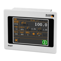
Figure 1: P40T - Touch Panel
10
5 Product Features
10
Dimensions
11
Figure 2: Type Label
11
Figure 3: Dimensions P40T
11
Identification
11
6 Technical Data
11
Technical Data
12
7 Installation and First Start-Up
13
Operating Area
13
Activation of the Device
14
Figure 4: Mounting into Panel Cut-Out
14
Mounting of the Controller
14
8 Design und Function
15
Figure 5: Menu Structure
15
Menu Structure
15
Figure 6: Start Screen / Main Menu
16
Figure 7: Language Selection
16
Language Selection
16
9 Main Menu
16
Figure 8: Single Mode
17
Figure 9: Numerical Input Fields of Axis Parameters
17
10 Operation Modes
17
Single Mode
17
Figure 10: Select Material from List
18
Figure 11: Piece Counter Selection Mask
18
Figure 12: Downwards Piece Counter
19
Figure 13: Upwards Piece Counter
19
Figure 14: Piece Counter Disabled
20
Figure 15: Manual Inching Mode
20
Manual Mode
20
Figure 16: Program Mode and Program List
21
Program Mode
21
Figure 17: Numeric and Alphanumeric Input Field
22
Figure 18: Define the "End of Program
23
Reference an Axis
24
Figure 19: Main Page Service
25
Figure 20: Password Login
25
Password Login
25
Service Menu
25
11 Service Mode / Parameter Level
25
Figure 21: Sub Menu Axis
26
Sub Menu Axis
26
Figure 22: Settings Axis (General)
27
Settings Axis
27
Table 1: Define Type of Axes
28
Distances Axis
32
Figure 23: Axis Distances
32
Figure 24: Creep Speed (1 Speed)
33
Figure 25: Creep Speed (2 Speeds)
34
Figure 26: Creep and Slow Speed (3 Speeds)
34
Figure 27: Axis Times
37
Times Axis
37
Analog Axis
39
Figure 28: Axis Analog
39
Calibrate Axis
43
Figure 29: Axis Calibration with Axis Angle
43
Figure 30: Calibration Without Axis Angle
44
Figure 31: Sub Menu Cutting
45
Sub Menu Cutting
45
Figure 32: System General
47
Sub Menu Setting System
47
Figure 33: System Times
49
Sub Menu Times System
49
Additional Functions
52
Figure 34: Additional Functions
52
Figure 35: Main Menu - Pump Is off
53
Figure 36: Main Menu - Pump Is on
53
Figure 37: Example Singe Mode - Pump Status in the Info Line
53
Pump Control
53
Calibrate (Touch Screen)
54
Figure 38: Calibration Touch Screen
54
Figure 39: Soft-Keys
55
Soft Keys
55
Table 2: Soft Keys
55
Figure 40: Material Table / List
57
Material Table
57
Table 3: Interpolation Procedure
58
Figure 41: Logic Assignment of Input / Output Functions
59
Functional and Logical Assignment of Input-/Output Functions
59
Figure 42: Load and Save OEM Data
60
Figure 43: Load Default Parameters
60
Load and Save OEM Data
60
Reset to Factory Defaults
60
Figure 44: Touchscreen Design
61
Figure 45: Activate PC Interface
61
PC Interface
61
Touchscreen Design / Program Version / Backup ID
61
12 Connections
62
Connector Arrangement - 16 IO Version
62
Figure 46: Connector Arrangement - 16 IO
62
Pin Assignment - 16 IO Version
63
Connector Arrangement - 8 IO Version
64
Figure 47: Connector Arrangement - 8 IO
64
Pin Assignment - 8 IO Version
65
Parameter Setting System
66
Parameter Sub Menu Axes
66
13 Parameter Tables
66
Parameter Times System
66
Table 4: Parameter List - Setting System
66
Table 5: Parameter List - Time System
66
Table 6: Parameter List - Axis Backgauge
66
Table 7: Parameter List - Axis Gap
67
Table 8: Parameter List - Setting Angle
67
Table 10: Parameter List - Distance Axis Gap
68
Table 11: Parameter List - Distance Axis Angle
68
Table 9: Parameter List - Distance Axis Backgauge
68
Table 12: Parameter List - Time Axis Backgauge
69
Table 13: Parameter List - Time Axis Gap
69
Table 14: Parameter List - Time Axis Angle
69
Parameter Sub Menu Additional Functions
70
Parameter Sub Menu Cutting
70
Table 15: Parameter List - Analog Axis
70
Table 16: Parameter List - Sub Menu Cutting
70
Table 17: Parameter List - Sub Menu Additional Functions
70
Parameter Digitale In-/Output
71
Parameter Material Table
71
Parameter Sub Menu Soft Keys
71
Table 18: Parameter List - Sub Menu Soft Keys
71
Table 19: Parameter List - Material Table
71
Table 20: Parameter List - Digital Inputs at ST3
71
Table 21: Parameter List - Digital Inputs at ST4
71
Table 22: Parameter List - Digital Output at ST5
72
Table 23: Parameter List - Digital Outputs ST6
72
14 Disturbances, Maintenance, Cleaning
73
Fault Clearance
73
Possible Errors and Their Clearance
74
Table 24: Possible Errors and Their Clearance
74
Cleaning
75
Maintenance
75
Re-Start after Fault Clearance
75
15 Type Designation
76
Accessories
77
Table 25: Accessories
77
16 Appendix
78
17 Index
86
Need help?
Do you have a question about the Elgo P40T-002 Series and is the answer not in the manual?
Ask a question
Elgo P40T-002 Series Specifications
General
Brand
Elgo
Model
P40T-002 Series
Category
Controller
Language
English