Do you have a question about the Elite EN46275900 and is the answer not in the manual?
Ensure power is off and the unit is cool before commencing installation procedures.
Remove screws from the motor enclosure assembly to gain access to the motor compartment.
Remove electrical box cover, separate wires, and disconnect conduit from the old motor.
Unfasten nuts securing the fan/motor assembly and carefully remove it from the housing.
Use a 1/8" Allen key to remove the blower wheel and the flat plate from the motor.
Use a 5/64" Allen key to detach the heat slinger from the motor assembly.
Remove lock nuts from the motor base plate and detach the base plate.
Remove any accumulated debris from the blower wheel for optimal performance.
Check blower wheel for broken or missing fins; replace if any defects are found.
Reassemble the motor by attaching the base plate, heat slinger, and flat plate correctly.
Properly set and secure the heat slinger to the motor shaft using a 5/64" Allen key.
Slide the flat plate onto the motor shaft with the beveled side up for proper slinger spin.
Mount the blower wheel onto the motor shaft, set its height, and secure it with a 1/8" Allen key.
Align motor bracket holes with SWG housing studs and reattach the motor assembly.
Connect conduit, join wires using wire nuts, and replace the electrical box cover.
Apply high-temperature silicon to seal the motor bracket assembly where it meets the SWG housing.
Secure the motor cover back over the assembly by aligning and fastening the screw holes.
Restore power, simulate a heat call, and inspect the unit for proper operation.
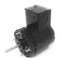
The EN46275900 is an aftermarket replacement motor designed for specific Field Controls Side Wall Venters, including models SWGII-4HD, SWG-4HD, and SWG-4HDS (which encompass SWG-4HDRMK and SWG-4RMK). This motor serves as a direct replacement component to restore the functionality of these power venter units.
The primary function of the EN46275900 motor is to drive the blower wheel within the side wall venter assembly. This action is crucial for the proper operation of the venter, which is responsible for exhausting combustion gases from heating appliances. By creating airflow, the motor ensures that the venter effectively draws out flue gases, maintaining safe and efficient operation of the connected heating system. The motor is a sealed bearing type, which generally implies enhanced durability and reduced maintenance requirements compared to open-bearing designs.
The replacement motor included in the EN46275900 package has the following key specifications:
The package also includes essential accessories for installation:
The installation process for the EN46275900 motor is detailed and requires careful execution to ensure proper function and safety. Key steps include:
The manual highlights the importance of regular maintenance for the fan and motor assembly:
Endeavoring Enterprises provides a limited warranty for the EN46275900, covering defects for a period of 12 months from the date of purchase. It's important to note that labor charges are not covered under this warranty. The manufacturer explicitly states that it is not liable for incidental or considerable damages resulting from the use of this product.
The manual includes a crucial warning: "For your protection, read and follow these instructions carefully before installing the motor. These instructions do not attempt to cover all installation and situations. If you do not understand these instructions or additional information is required, contact Endeavoring Enterprises. The EN46275900 must be installed by a qualified technician familiar with the local codes, construction and operation of this type of product. To avoid electric shock, serious injury, or death, be certain that all electrical power is disconnected before installing or servicing your power venter." This emphasizes the importance of professional installation and adherence to safety protocols.