EasyManua.ls Logo

Elite RC-1 - User Manual

Elite RC-1
3 pages
Print Icon
To Next Page IconTo Next Page
Loading...
Page 1 of 3
ELITE Simulation Solutions
5700 Dot Com Court, Suite 1010
Oviedo, FL 32765
407-359-8787
ELITE Simulation Solutions
RC-1 Computer Mounting and Connection Guide
Thank you for choosing ELITE Simulation Solutions for your flight simulation needs!
This document will provide you with the necessary instructions for preparing the
computer setup that will power your RC-1 AATD.
Below is an image of the pre-mounted computer assembly, with very minor variations
depending on part availability:
Two Mac Mini computers are mounted onto the plexiglass, a main computer labeled
“ELITE RC-1” which powers the simulator, and a visual computer labeled “ELITE Visual”
which powers the visual. Out of the box, they should already be connected to their
power adapters, which are also mounted in place, and plugged into the surge protector.
The computers are also connected together by a CAT-6 crossover network cable, which
allows them to communicate with each other.
The first thing that you would need to do is to place this assembly into position onto the
lower rack in the nose of the simulator.
Question and Answer IconNeed help?

Do you have a question about the Elite RC-1 and is the answer not in the manual?

Summary

Computer Assembly and Initial Setup

Overview of Mac Mini Configuration

Details the two Mac Mini computers, their roles (RC-1, Visual), and their pre-connected power and network setup.

Simulator Base Installation

Instructions for placing the assembled computer unit into the simulator's lower rack.

Connecting Video and Control Hardware

Video Output Connections

Guides connecting video ports (Instructor, Instrument, Engine) to their respective cockpit displays.

Flight Control Hardware Integration

Explains connecting flight controls (console, panel, pedals) via USB to the main computer's hub.

Software Activation and System Power-Up

WIBU Key Installation

Describes plugging the WIBU key USB dongle into the main computer for software licensing.

Visual Display and System Power

Connects the visual computer to an external display and details the system power-on procedure.

Overview

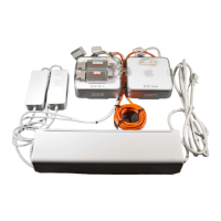
This document describes the ELITE Simulation Solutions RC-1 Computer Mounting and Connection Guide, detailing the setup and connection of the computer system for the RC-1 AATD (Advanced Aviation Training Device).

Function Description

The ELITE RC-1 computer system is designed to power the RC-1 AATD flight simulator. It consists of two Mac Mini computers: a "main computer" labeled "ELITE RC-1" and a "visual computer" labeled "ELITE Visual." The main computer handles the core simulator functions, including instrument display, engine indicators, and flight control hardware. The visual computer is dedicated to generating and displaying the external visual environment of the simulator, typically connected to a television or projector. The system is pre-mounted on a plexiglass assembly, with power adapters and a surge protector already integrated.

Important Technical Specifications

  • Computer Type: Two Mac Mini computers.
  • Mounting: Pre-mounted on a plexiglass assembly.
  • Power: Power adapters for both computers are mounted and plugged into an integrated surge protector.
  • Network Connection: The two computers are connected via a CAT-6 crossover network cable for communication.
  • Video Outputs (Main Computer):
    • Instructor Port: Connects to the instructor station monitor.
    • Instrument Port: Connects to a 17-inch monitor in the cockpit for primary instruments. This port is an external video card connected via USB.
    • Engine Port: Connects to a 15-inch monitor in the cockpit for engine instruments and other indicators. This port is also an external video card connected via USB.
  • Video Output (Visual Computer):
    • Visual Port: Connects to an external display device (television or projector) for the simulator's visual environment.
  • USB Connectivity: ELITE flight control hardware (flight console, avionics panel, rudder pedals) connect to a USB hub attached to the back of the main computer.
  • Software Activation: Requires a teal-colored USB dongle (WIBU key) to be plugged into a USB port on the main computer for ELITE software functionality.

Usage Features

Initial Setup:

  1. Placement: The entire computer assembly should be placed onto the lower rack in the nose of the simulator.
  2. Video Connections (Main Computer):
    • Connect the "Instructor" port to the instructor station monitor.
    • Connect the "Instrument" port to the 17-inch cockpit monitor (left side).
    • Connect the "Engine" port to the 15-inch cockpit monitor (next to the instrument monitor).
  3. Flight Control Hardware Connection:
    • Connect the ELITE flight console, avionics panel, and rudder pedals to the USB hub attached to the back of the main computer.
    • Run a USB cable from the hub to the instructor station monitor to connect the keyboard and mouse, utilizing the monitor's built-in ports.
  4. Software Dongle: Ensure the teal-colored USB WIBU key is plugged into a USB port on the main computer.
  5. Visual Computer Connection: Connect the "Visual" port of the visual computer to the external display device (television or projector).
  6. Power Connection: Once all construction and connections are complete, connect the surge protector to an electrical outlet. If necessary, move the power switch on the surge protector to the "Reset" position.

Operation:

  • Automatic Power-On: Once power is supplied, the computers should automatically turn on.
  • Manual Power-On: If a computer does not turn on automatically, press the power button located on the rear of its chassis.
  • Hardware Recognition: The system may take a few minutes to recognize the connected hardware for the first time.
  • Starting Simulation: After initial recognition, click the "ELITE" icon on the desktop to start the simulator.

Maintenance Features

  • Pre-labeled Ports: Video ports are pre-labeled to simplify initial setup and any future troubleshooting of connections.
  • Integrated Power Management: Power adapters for both computers are pre-mounted and connected to a surge protector, offering a consolidated and protected power solution.
  • Modular Design: The use of Mac Mini computers and external video cards for specific displays suggests a modular design that could facilitate component replacement if needed, though this is not explicitly detailed as a user-serviceable feature.
  • USB Connectivity: The reliance on USB for flight control hardware and external video cards simplifies connections and potentially allows for easier diagnosis of peripheral issues.
  • WIBU Key: The physical WIBU key serves as a clear indicator for software activation, making it easy to verify if the software is enabled or if the key is missing/misplaced.
  • Troubleshooting: The guide provides basic troubleshooting steps for power-on issues (manual power button) and emphasizes the importance of the WIBU key for software functionality.

Elite RC-1 Specifications

General IconGeneral
BrandElite
ModelRC-1
CategoryDesktop
LanguageEnglish