3 EWTR/HR/PR 910 12/96 ing
in 0 or 5 only, or in all 10 digits.
hdd = n : e.g. 070, 071, 072 etc. (if with-
out decimal point) or 70.0, 70.1, 70.2 etc.
(if with decimal point);
hdd = y : e.g. 070, 075, 080, etc. (if with-
out decimal point) or 70.0, 70.5, 71,0, etc.
(if with decimal point). Useful when mea-
suring values varying rapidly (e.g. %R.H.).
tAb: tAble of parameters.
This shows the configuration of the para-
meters as set in the factory; can not be
modified (for factory identification and di-
agnostic purposes only).
PROPORTIONAL CONTROL
In the event that the factory set parameter
values in a PID temperature controller do
not give optimum results, the following
steps may be followed to enhance the op-
eration for each specific application:
» select a value for Setpoint which will keep
the temperature swing within acceptable
limits, for example 10% below the normal
operating temperature;
» set the switching differential (“d1”) at 3%
of the setpoint temperature;
» start the system and wait for the temper-
ature swings to become constant;
» check the process temperature (use a
data recorder if possible) at regular inter-
vals; determine the time between two suc-
cessive temperature peaks (Tu) as well as
the total temperature swing (dT).
Parameters “Pb”, “It”, “dt” and “Ct” can
now be calculated as follows:
Pb = 2xdT; It = Tu/2; dt = Tu/8; Ct = Tu/20.
Additional fine tuning of the above para-
meters may be tried, keeping in mind how-
ever the following:
- the “Proportional action” activates the
output in direct proportion to the shift in
stable system temperature;
- the “Derivative action” effects the output
depending on the speed of temperature
change;
- the “Integral action” activates the output
in proportion to the continuous integral cal-
culation of the deviation values.
As a result:
a) an increase in the proportional band
width reduces the temperature swing, but
increases the shift in stable system tem-
perature;
b) an excessive reduction of the propor-
tional band width reduces deviation, but
will also make the system less stable;
c) an increase in the derivative time re-
duces temperature swings when the sys-
tem has become stable, but may cause
wider temperature swings and increased
deviation from setpoint;
d) an increase in the integral time reduces
the deviation between setpoint and system
value when system has become stable;
e) a weak integral action always has a tem-
perature deviation which, in general, can
be eliminated by reducing the proportional
band width and by increasing first of all the
derivative action, then the integral action.
INSTALLATION
The instrument is designed for flush panel
mounting; the required panel cut-out is
67x67 mm (2.64x2.64"). Insert the instru-
ment from the front and tighten from the
rear with the two mounting brackets pro-
vided.
The ambient temperature around the in-
strument should be kept between –5 and
65 °C (23 and 149 °F). Select a location
which will not be subject to high humidity
or condensation and allow some ventila-
tion to provide cooling to the instrument.
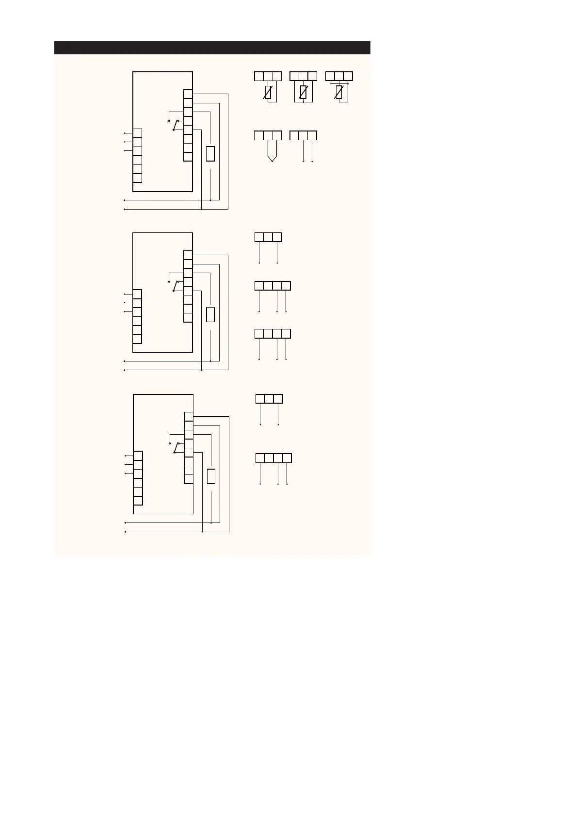
ELECTRICAL WIRING
Two quick-disconnect terminals are pro-
vided for easy and convenient wiring, even
before the instrument is actually installed.
Make sure that the power supply corre-
sponds with the rating shown on the in-
strument; the power supply must be kept
within plus or minus 15% of the nameplate
voltage.
Separate the wiring of the input signals
from those of the power supply and
switched output wiring.
The relay output contacts are voltage free
and independent ; do not exceed the re-
sistive rating of 8 Amp at 250 Vac. For larg-
er loads, please use an external contactor
or relay.
ERROR ANNOUNCIATION
Any sensor input defect will be displayed
as follows: “---” in case of shorted sensor;
“EEE” in case of sensor break, or sensor
absence.
The “EEE” error message also appears in
 Loading...