Page 8
Elkay Manufacturing Company (630) 574-8484
2000000694 (Rev. A - 07/22)
ECH8_1P ECH8_2P ECH8_3P
6. Preparation
6.1 General Information
1. This Remote Chiller is designed for indoor use only
and should not be installed outdoors or in a humid
environment.
2. Usecarewhenopeningandremovingthe
packaging to prevent damage to the product.
a. Inspect the product for any shipping damage
and report it immediately to the location of
purchase.Installationofadamagedproductwill
voidthewarranty.
b. Conrmthatallpartshavebeenincludedforthe
proper installation of this product. Contact the
location of purchase if damaged parts are found.
NOTICE
Make sure no electrical wiring,
potable water inlet pipes, or
drain water outlet pipes will be damaged during
installation of the product. Damage to any of
these items can cause electrical damage, re,
and/or water damage.
3. Shutothewatersupplysourceanddisconnect
powertotheelectricaloutletbeingusedtooperate
the product before starting installation.
NOTICE
Mounting hardware to be
supplied by customer.
4. It is important to ensure proper ventilation.
5. When mounting in an open area, to ensure proper
ventilation,maintaina4"(102mm)clearancefrom
cabinet louvers on each side of chiller. When
mountingunitinacavityorbehindawall,maintain
aminimumspaceof4"(102mm)oneachside,4"
(102mm)onthetopandadepthof12"(305mm).
6. Waterinletis3/8”(10mm)O.D.unplatedtube.
Contractor to supply connections as required.
7. Connecting lines to be made of unplated copper.
Thoroughlyushalllinestoremoveallforeign
matter before connecting to chiller. If flushing does
notremoveallparticles,awaterstrainershouldbe
installed in supply line. This chiller is manufactured
insuchamannerthatitdoesnotinanywaycause
taste, odor, color or sediment problems.
8. Connectchillertobuildingsupplywithashut-o
valve and installthein-linestrainerbetweenthe
valve and chiller.
9. Electrical:Makesurepowersupplyisidentical
involtage,cycle,andphasetothatspeciedon
chiller serial plate.Neverwirethecompressor
directlytothepowersupply.
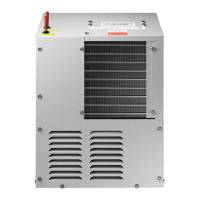
7. Installation: Electrical connection
1. Turnoelectricalsupplytochillercircuit.
2. Remove the front panel to gain access to electrical
boxusinga5/16"(7.9mm)socketwrenchora
atheadscrewdriver.
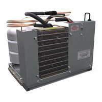
3. Rotate the fan to ensure a proper clearance and
free fan action.
4. Use3/8”cableclampconnectororappropriate
conduitconnectorwithnuttoconnecttheelectrical
wiretotheunit.
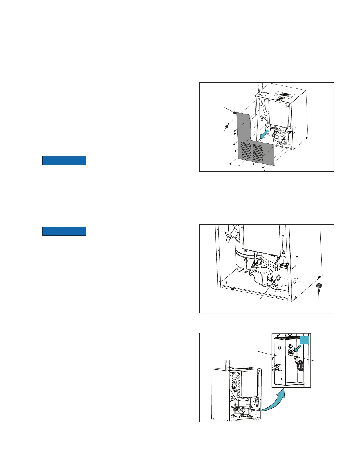
5. Connectgroundwire(A)togroundscrew(provided).
Conduit
Connector
Nut
Screw
Front Panel
Ground
Wire
Electrical
Box
 Loading...