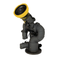
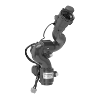
EasyManua.ls Logo

ELKHART BRASS Cobra EXM2 Series User Manual

ELKHART BRASS Cobra EXM2 Series
40 pages
To Next Page IconTo Next Page
Page #1 background imageLoading...
Page #1 background image
98608000 REV-REL Cobra EXM2 Monitor Shown
Installation, Operating, & Maintenance Instructions
1-574-295-8330
www.elkhartbrass.com

Table of Contents

Questions and Answers:

ELKHART BRASS Cobra EXM2 Series Specifications

General IconGeneral
BrandELKHART BRASS
ModelCobra EXM2 Series
CategoryMonitor
LanguageEnglish

Summary

MAINTENANCE INSTRUCTIONS

Preventive Maintenance

Routine checks and greasing procedures for the monitor and control system.

TROUBLESHOOTING GUIDE

Understanding System LEDs

Explains monitor LED blink patterns indicating errors and safe mode conditions.

PRODUCT SAFETY INFORMATION

General Safety Precautions

Essential safety precautions and warnings for operating the equipment.

SYSTEM INFORMATION

EXM2 MONITOR FEATURE CALLOUTS

SYSTEM COMPONENTS

EXM2 Monitors

Describes the general design and control methods for EXM2 monitors.

CONTROL

Joystick Controller – 7030X2

Details the operation and features of the joystick controller for monitor functions.

Panel Mount Controller - 7010X2

Describes the panel mount controller with push-button operation for monitor and valve control.

Handheld Controller, Docking Station, and RF Gateway

Explains the wireless handheld controller, docking station, and RF gateway functionality.

MONITOR & VALVE ACCESSORIES

Position Feedback Display – 7051X2

Describes the position feedback display that shows monitor orientation.

Unibody Valve with Electric Actuator

Details the electric actuated unibody valve for remote control of water supply.

INSTALLATION INSTRUCTIONS

Installation Overview

Provides general guidance and electrical requirements for EXM2 monitor installation.

Recommended electrical requirements for EXM2 input devices

Specifies wire gauge, amperage, and shielding for input devices like controllers.

Termination Points

Explains the importance and placement of termination points in the CAN communication network.

Mount and Wire All System Components

Guides on mounting the monitor, connecting power, and CAN lines.

EXM2 Wiring Connections

Illustrates various wiring harnesses and their connections for EXM2 system components.

Harness A - Controller Pigtail

Pigtail harness for Panel mount, Position Display, and Joystick.

Harness B - Monitor Pigtail

Pigtail harness for the EXM2 monitor.

Harness C - Valve Pigtail

Pigtail harness for the E14X/E16X actuated valve.

EXM2 Harnesses Overview

Covers optional EXM2 harnesses like extension, splitter, and termination plugs.

Harness E - EXM2 Extension harness

Optional extension harness for connecting EXM2 components.

Harness F - CAN Splitter

Optional CAN Y splitter for network configuration.

Panel Mount Controller Installation

Details the mounting, wiring, and power supply for the panel mount controller.

Handheld Controller, Gateway and Docking Station

Guides on mounting and connecting handheld, gateway, and docking station.

Joystick Controller Installation

Guides on mounting and connecting the joystick controller to the CAN line.

Position Feedback Display Installation

Details mounting, wiring, and power for the position feedback display.

Electric Actuated Unibody Valve Installation

Guides on installing, wiring, and powering the electric actuated unibody valve.

Configure the EXM2 System

Explains when system configuration is needed and where to find instructions.

Calibrate the EXM2 System

Outlines the necessity and process of calibrating the EXM2 monitor's rotation.

Setup Mode with Controllers

Describes how to enter and use Setup Mode for calibration and configuration.

Calibrating Horizontal and Vertical Rotation

Details the procedure for calibrating the monitor's horizontal and vertical movement.

Calibrate Valve

Describes the procedure for calibrating the Elkhart Brass Unibody valve.

Calibrate Position Display

Explains how to calibrate the position display to show accurate monitor movements.

Final Check

Guides on performing a final verification of the installed EXM2 system.

EXM2 Motor Currents

Stow Output

Proximity Sensor for Extended Travel

Nozzles

Configure the EXM2 System

Explains when system configuration is needed and where to find instructions.

OPERATING INSTRUCTIONS

Button / Joystick Operation

Explains the function of each button and joystick control for operating the monitor.

LED Meanings

Interprets the status and operational meaning of the LEDs on the monitor and controllers.

Monitor LEDs in Setup Mode

Describes LED behavior when the system is in Setup Mode.

Input Controller LEDs (General)

Explains general LED indicators on input controllers like Stow, Deploy, Open, Close, Preset.

Panel Mount and Handheld Specific LEDs

Details specific LEDs for Panel Mount and Handheld controllers (OSC, AUX, EXT).

Panel Mount STATUS LED

Explains color meanings for the Panel Mount STATUS LED (Off, Green, Blue, Yellow, Magenta).

Wireless Handheld POWER LED

Describes the power LED status on the wireless handheld, indicating battery level and charging status.

Wireless Handheld Specific LEDs (Pairing)

Details LEDs related to RF pairing and clearing previous pairings on the handheld.

Wireless Handheld STATUS LED

Explains color meanings for the wireless handheld STATUS LED (Off, Green, Blue, Yellow, Magenta, Red-yellow, Red).

Joystick STATUS LED

Explains color meanings for the Joystick STATUS LED and error blink patterns.

Docking Station LEDs

Describes LED status on the docking station for power and charging.

Setup Mode

Explains the prerequisite of entering Setup Mode for system programming and configuration.

Re-calibrating Horizontal and Vertical Rotation

Provides steps to re-calibrate the monitor's horizontal and vertical movement if needed.

Travel Limits

Details how to set horizontal and vertical travel limits for the monitor's motion.

Extended Travel

Explains the extended vertical travel functionality for Cobra & Boa EXM2 using a proximity sensor.

Keep-Out Zones

Guides on setting keep-out zones to restrict monitor movement in specific areas.

Stow Position

Describes how to set and program a desired stow position for the monitor.

Deploy Position

Explains how to set and program a desired deploy position for the monitor.

Motor Speed

Details how to adjust motor speeds (Fast/Slow) for horizontal and vertical movement.

Clear All Function

Explains how to clear set Travel Limits, Keep-Out Zones, and Stow Positions.

Oscillation

Guides on setting up and using the oscillation function for repetitive monitor movement.

Valve Operation

Explains how to operate the electric valve (Open, Close, Preset, Trigger).

TROUBLESHOOTING GUIDE

Understanding System LEDs

Explains monitor LED blink patterns indicating errors and safe mode conditions.

Panel Mount STATUS LED

Details color meanings for the Panel Mount STATUS LED and error blink patterns.

Panel Mount Controller LEDs

Describes Panel Mount LEDs for power, status, and error conditions.

Wireless Handheld STATUS LED

Explains color meanings for the wireless handheld STATUS LED and error blink patterns.

Joystick STATUS LED

Explains color meanings for the Joystick STATUS LED and error blink patterns.

Docking Station LEDs

Describes LED status on the docking station for power and charging.

RF-CAN Gateway LED

Explains the LED indicators on the RF-CAN Gateway for power, pairing, and communication.

OPTIONAL ACCESSORY SPECIFICATIONS

Panel Mount Controller – 7010X2 Specs

Lists specifications for the Panel Mount Controller.

Joystick Controller – 7030X2 Specs

Lists specifications for the Joystick Controller.

Handheld Controller – 7015X2WH Specs

Provides specifications for the handheld controller, including battery life.

Docking Station – 7015X2DS Specs

Lists specifications for the docking station, including power and environmental ratings.

Gateway - 7015X2GW Specs

Lists specifications for the Gateway, including RF power output.

Valve Controller – E14X/E16X Specs

Provides specifications for the Valve Controller, including input power and fuse rating.

Position Display – 7051X2 Specs

Lists specifications for the Position Display, including input power and dimensions.

Gateway

Gateway FCC and ISED Statements

Contains FCC and ISED statements and approved antenna list for the Gateway.

Handheld

Handheld FCC and ISED Statements

Provides FCC and ISED statements for the Handheld controller.

Related product manuals