EasyManua.ls Logo

Eller PT - Trolley Installation and Test Run; Maintenance and Specifications; Maintenance Schedule; Technical Specifications and Dimensions

Eller PT
Print Icon
To Next Page IconTo Next Page
To Previous Page IconTo Previous Page
Loading...
3. When a clearance of 1-1.5 mm has been achieved between the wheels and the flange, the
trolley can be installed on the beam and the nuts fastened and secured by the split pin.
4. Ensure that endstops are fitted to the runway, so that the trolley cannot run off.
5. Before applying a load to the trolley, make a test-run to be sure it runs smoothly back and forth
along the entire runway.
6. The hoist may now be hooked on and the combination put into operation.
V. Maintenance and inspection
The trolley is maintenance free.
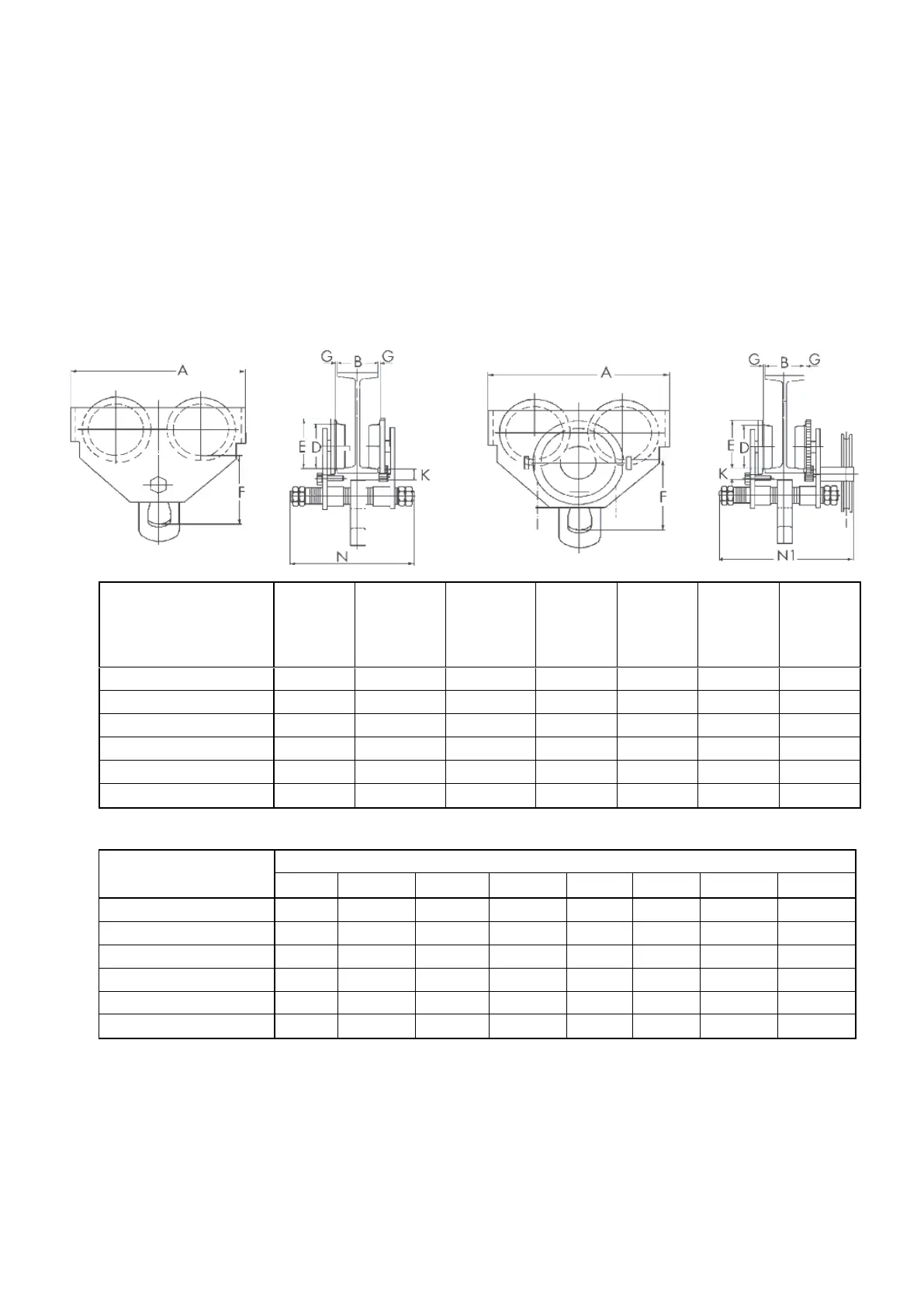
VI. Specification
Article code
Safe
Working
Load (t)
Adjustable
beam width
PT B (mm)
Adjustable
beam width
GT B (mm)
Min.
Radius
(m)
Hand
chain (m)
Weight
PT (kg)
Weight
GT (kg)
ELPT005 / ELGT005
0,5
50 - 203
64 - 203
0,8
2,5
7
14,5
ELPT010 / ELGT010
1
64 - 203
64 - 203
0,9
2,5
10,5
14,5
ELPT020 / ELGT020
2
88 - 203
88 - 203
1
2,5
17,5
21,5
ELPT030 / ELGT030
3
100 - 203
100 - 203
1,2
2,5
27
31
ELPT050 / ELGT050
5
114 - 203
114 - 203
1,3
2,5
41
46
ELPT100 / ELGT100
10
124 - 203
124 - 203
1,7
2,5
48
95
Article code
Measurements (mm)
A
D
E
F
G
K
N
N1
ELPT005 / ELGT005
199
55
67
105
2
30
295
326
ELPT010 / ELGT010
246
68
81,5
125
2
38
311
338
ELPT020 / ELGT020
276
80
94
150
2
38
327
349
ELPT030 / ELGT030
332
100
115,5
171
3
40
343
362
ELPT050 / ELGT050
377
110
127
196
3
42
355
374
ELPT100 / ELGT100
389
136
156
285
3
22
403
480
PT
GT