Setting the Headers (continued)
38 of 76
ELM327DSH Elm Electronics – Circuits for the Hobbyist
www.elmelectronics.com
Electronics does not maintain lists of this information,
and cannot provide any further details for you. Mode
22 and others are described in more detail in the SAE
standards document J2190, ‘Enhanced E/E Diagnostic
Test Modes’.
The ISO14230-4 standard defines its header bytes
a little differently. Advanced experimenters will be
aware that for ISO 14230-4, the first header byte must
always include the length of the data field, which
varies from message to message. From that, one
might assume that the you would need to redefine the
header for every message that is to be sent – not so!
The ELM327 always determines the number of bytes
that you are sending, and inserts that length for you, in
the proper place for the header that you are using. If
you are using the standard ISO 14230-4 header, the
length will be put into the first header byte, and you
need only provide the two (most significant) bits of this
byte when defining the header. What you place in the
rest of the byte will be ignored by the ELM327 unless
you set it to 0. If it is 0, it is assumed that you are
experimenting with KWP four byte headers, and the
ELM327 then creates the fourth header byte for you.
Again, you do not need to provide any length to be put
into this byte – it is done for you.
Addressing within the CAN (ISO 15765-4)
protocols is quite similar in many ways. First, consider
the 29 bit standard. The ELM327 splits the 29 bits into
a CAN Priority byte and the three header bytes that we
are now familiar with. This is how they are combined
for use by the ELM327:
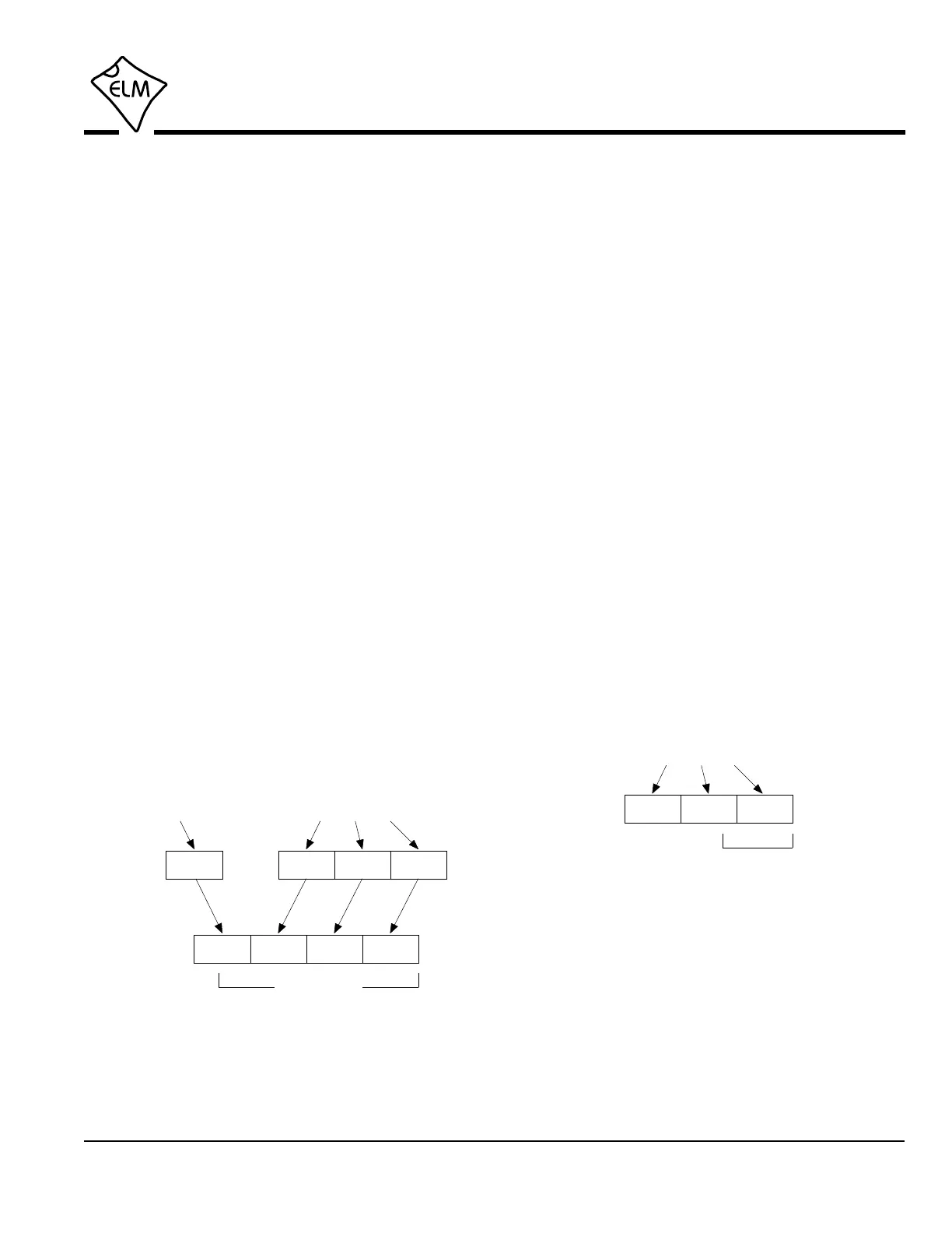
>AT SH xx yy zz>AT CP vv
vv xx yy zz
5 bits only
xx yy zzvv
29 bit ID
Setting a 29 bit (extended) CAN ID
The CAN standard states that for diagnostics, the
priority byte (‘vv’ in the diagram) will always be 18 (it is
the default value used by the ELM327). Since it is
rarely changed, it is assigned separately from the
other header bytes, using the CP command.
The next byte (‘xx’) describes the type of message
that this is, and is set to hex DB for functional
addressing, and to DA if using physical addressing.
The next two bytes are as defined previously for the
other standards – ‘yy’ is the receiver (or Target
Address), and ‘zz’ is the transmitter (or Source
Address). For the functional diagnostic requests, the
receiver is always 33, and the transmitter is F1, which
is very similar to ISO 14230-4.
Those that are familiar with the SAE J1939
standard will likely find this header structure to be very
similar (J1939 is a CAN standard for use by ‘heavy-
duty vehicles’ such as trucks and buses). It uses
slightly different terminology, but there is a direct
parallel between the bytes used by J1939 for the
headers and the grouping of the bytes in the ELM327.
Pages 48 and 49 provide more details of the J1939
message structure.
The final header format to discuss is that used in
11 bit CAN systems. They also use a priority/address
structure, but shorten it into roughly three nibbles
rather than three bytes. The ELM327 uses the same
commands to set these values as for other headers,
except that it only uses the 11 least significant (‘right-
most’) bits of the provided header bytes, and ignores
the others, as shown here:
xx yy zz
11 bit ID
>AT SH xx yy zz
Setting an 11 bit (standard) CAN ID
It quickly becomes inconvenient to have to enter
six digits when only three are required, so there is a
special ‘short’ version of the AT SH command that
uses only three hex digits. It actually operates by
simply adding the leading zeros for you.
The 11 bit CAN standard typically makes
functional requests (ID/header = 7DF), but receives
physical replies (7En). With headers turned on, it is a
simple matter to learn the address of the module that
is replying, then use that information to make physical
 Loading...