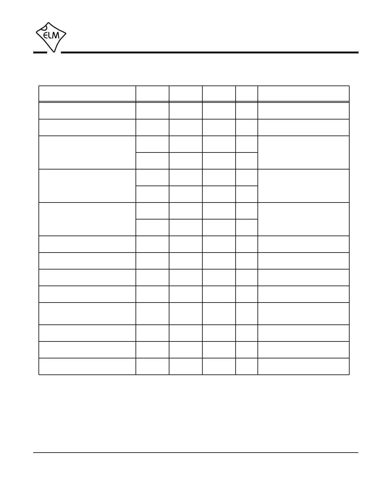
Electrical Characteristics
6 of 76ELM327DSH Elm Electronics – Circuits for the Hobbyist
www.elmelectronics.com
Notes:
1. This integrated circuit is based on Microchip Technology Inc.’s PIC18F2480 device. For more detailed
device specifications, and possibly clarification of those given, please refer to the Microchip documentation
(available at http://www.microchip.com/).
2. This spec must be met in order to ensure that a correct power on reset occurs. It is quite easily achieved
using most common types of supplies, but may be violated if one uses a slowly varying supply voltage, as
may be obtained through direct connection to solar cells or some charge pump circuits.
3. This is the time between when the AT RV command is received, and when the voltage reading response
begins.
All values are for operation at 25°C and a 5V supply, unless otherwise noted. For further information, refer to note 1 below.
Characteristic Minimum Typical Maximum ConditionsUnits
Supply voltage, VDD 4.5 5.0 5.5 V
VDD rate of rise 0.05 V/ms
Average current, IDD
12 mA
Input logic levels 0.8
3.0
V
Output low voltage
Output high voltage
current (sink) = 10 mA
current (source) = 10 mA
see note 2
see note 3
ELM327 device only - does not
include any load currents
Schmitt trigger
input thresholds
Brown-out reset voltage 4.11 4.33 4.55 V
rising
falling
A/D conversion time 9 msec
Pins 5, 6, 7, and 24 only
V
V
0.3
4.4
V
V
2.9
1.5
Pins 1, 11, 12, 13, 15 and 18 only
1.0
4.0
IgnMon debounce time
AT LP to PwrCtrl output time
LP ALERT to PwrCtrl output time 2.0 sec
msec
sec
50
1.0
0.15 mA
normal
low power
Pin 18 low level pulse duration to
wake the IC from Low Power mode
µsec128 -
65
low
high VVDD
VSS
 Loading...