63 of 76
ELM327DSH Elm Electronics – Circuits for the Hobbyist
www.elmelectronics.com
switch all of the outputs as was described for the other
methods.
When connecting to pin 15, care should be taken
to not pass excessive current (>0.5 mA) through the
protection diodes, and the circuit should also provide
some filtering for ignition noise. Typically a circuit like
this works well (note that the Schmitt input on pin 15
allows the use of large value capacitors):
+12V switched
by the ignition
47KΩ
22KΩ0.1uF
The new AT IGN command can always be used to
read the level at pin 15, regardless of the setting of the
PP 0E enable bits. This may be used to advantage if
you wish to manually shut down the IC, using your
own timing and criteria. Recall that the alternate
function for pin 15 is the RTS input which will interrupt
any OBD processing that is in progress. If the
ELM327 reports an interrupt with the ‘STOPPED’
message, you can then check the level at pin 15 with
the AT IGN command, and make your own decisions
as to what should be done. For that matter, you don’t
even need to reduce the power based on the input -
you might possibly do something entirely different.
Having put the ELM327 into Low Power mode,
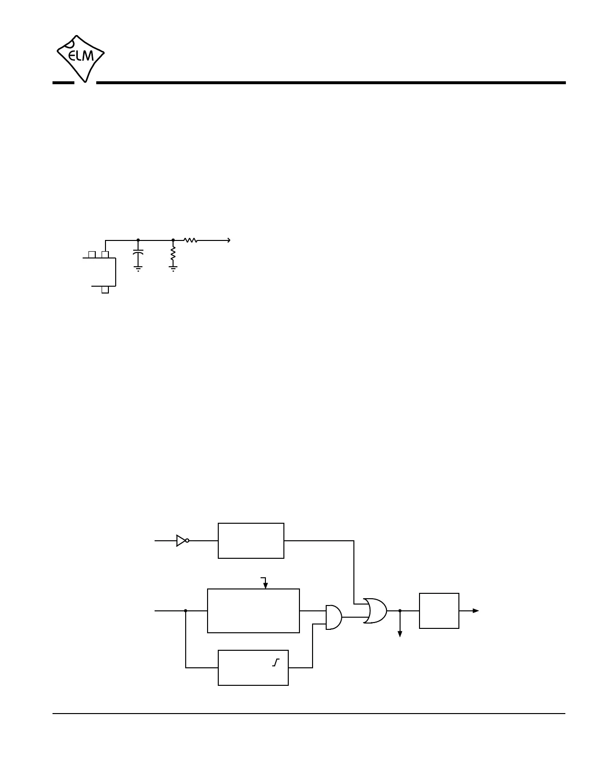
you will need a method to wake it up. This is done by
‘interrupting’ the IC in ways that are very similar to
what is done while monitoring. Refer to Figure 7 below
for a pictorial view of these methods.
Either a low level pulse at the RS232 Rx input, or
a low then high level at the IgnMon input will cause the
ELM327 to return to full power operation, and perform
a Warm Start reset. Note that PP 0E bit 2 does not
have to be set for the IgnMon to wake the circuit - the
ELM327 always monitors this pin, and will wake the
circuit after the delay that is set by PP 0E bit 1.
The RS232 input is not as sensitive as normal
when in the low power mode. For this reason, the
RS232 input pulse to wake the system must be at
least 128 usec wide. This is easily accomplished by
sending a space or @ character if the baud rate is less
than about 57.6 kbps, but when you use higher baud
rates, you may have trouble. For higher baud rates,
consider temporarily shifting to a lower baud rate, or
see if your software can generate a ‘break’ signal. If
you are directly connected to a microprocessor, then
you might want to generate your own break signal in
software.
This has discussed some of the software aspects
of using the new Power Control feature. Refer to the
‘Modifications for Low Power Standby Operation’
section (page 70) for a discussion of some of the
electrical design considerations.
Power Control (continued)
128 µsec min
pulse width
1 sec or 5 sec
time delay on pick up
(fast reset)
b1
rising edge ( )
was detected
1 sec
delay
perform a
warm start
(AT WS)
Go to Full Power
• µP to normal
• pin 16 = b6
RS232 Rx
(pin 18)
IgnMon
(pin 15)
Figure 7. Returning to Normal Operation
 Loading...