en
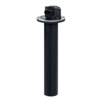
Ultrasonic sensor 2UF
Date: 28.06.2019 901A0004A01M - V03 5/7
6 Installation/putting into service
Observe the information and instructions of the
tank manufacturer.
Comply with the electrical specifications.
X Check the ultrasonic sensor and lead for
damage.
6.1 Mechanical connection
WARNING
Danger due to pressurised media
Escaping media can result in severe
injuries.
XX Ensure that the system is depres-
surised before the ultrasonic sensor
is installed/removed.
XX Check the container level.
XX If necessary, empty the tank before
the ultrasonic sensor is installed/
removed.
XX If necessary, wear personal pro-
tective equipment (safety gloves,
safety glasses).
XX Capture any escaping media in a
suitable vessel.
NOTICE
Danger due to incorrect installation
Ultrasonic sensors can be damaged
by overtightening (too high tightening
torques).
XX Avoid severe impacts or vibrations.
XX Adhere to the installation tolerances
and installation location.
XX Adhere to the tightening torques
(datasheet).
X Be aware of the influences of the medium!
Risk of incorrect measurements arising from:
● Foam formation
● Outgassing (e.g. with petrol), which changes
the physical properties of the air.
● Formation of condensation on the ultrasonic
transducer due to water and water vapour.
● Soiling of the ultrasonic transducer.
An inclined position upon installation reduces the
possible range.
X If necessary fit a suitable seal on the sealing
surface.
X Install the ultrasonic sensor in the tank using
screws. Adhere to the tightening torques in the
datasheet.
The focus tube can be shortened bearing in mind
the following information:
● The tube end must not be sloping.
● The tube end must be smooth and free from
fibres
● The interior of the tube must be clean
● Level measurements cannot be made when the
liquid surface is more than 8 mm beyond the
tube end
● When measurements are made more than
8 mm beyond the tube end the output signal is
undefined
● The electrical output signal, related to the abso-
lute measuring length, remains unchanged
● The useful range of the output signal is limited
dependent on the tube shortening
● The previous limit value of the output signal is
no longer reached at the new tube end
● The output signal at the shortened tube end is
equal to the output signal with the unshortened
tube if a measuring length corresponding to the
new tube length is set
6.2 Electrical connection
X Check for the voltage-free state of the connec-
tion.
X Connect the ultrasonic sensor in accordance
with the wire colours/connector pin assign-
ments in the data sheet.
X Route the wiring harnesses so that no damage
can arise (e.g. due to kinks, breaks, rubbing
points).
X Route wires so that they are rigidly fixed if
they will be exposed to temperatures less than
-5 °C.
X After installing, hand over the installation manu-
al to the end-user.
6.3 Putting into service
X Observe the information and instructions of the
ultrasonic sensor manufacturer.
X Ensure that the electrical specifications are
adhered to.
X Check the intactness of the sensor lead and
housing parts.
X Connect the operating voltage and check the
functioning of the ultrasonic sensor.
 Loading...