5
ww w.eltherm.com
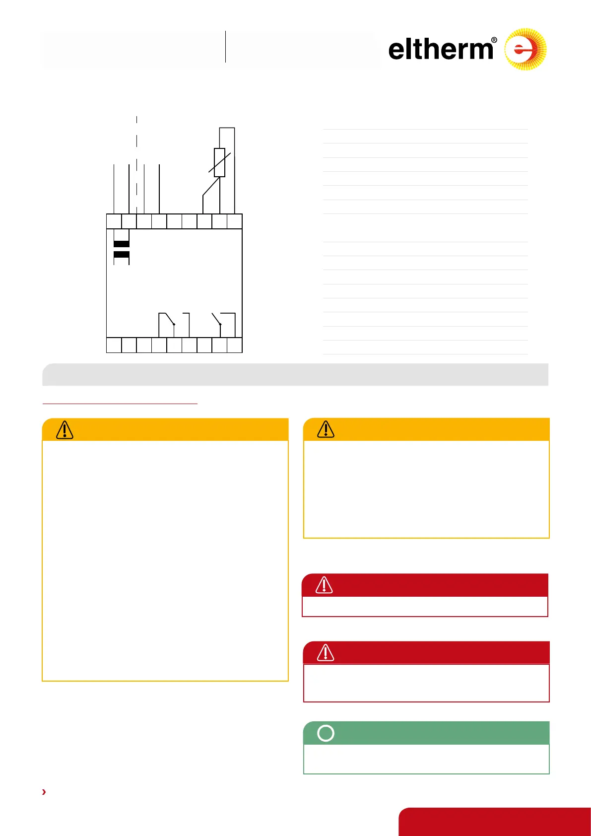
10 11 12 13 16 17 18
4 6 7 8 95
ELTC-21 only
230 VAC
L N
ELTC-22 only
24 VDC
+ -
K2
ALARM
K1
Heizung
Heater
Netz
Mains
*
Pt100
Contact us: +49 2736 4413-0 • info@eltherm.com
Operation manual
ELTC-21 & ELTC-22
BU-093
Revision 7
CONNECTION PLAN
SPECIAL NOTES
Installation and safety information
ATTENTION
• Electrical connection / commissioning must be carried
out by a qualied electrician.
• The relevant local safety regulations must be observed.
Observe the connection values according to the type
plate and these instructions.
• When selecting the installation site, observe the IP
protection class and permissible operating temperature.
Locations protected from direct precipitation and sunlight
are advantageous.
• Operation only with closed cover, tightened screw con-
nections / blind plugs and installed seals.
Avoid damage, tensile stress, kinking and torsion of the
connected lines.
• The sensor lines must be shielded when extended, the
shielding must be grounded on one side near the cont-
roller. The cable must not be laid parallel to lines carrying
mains voltage. The total line resistance must not exceed
10 ohms.
• Make sure that the connection terminals have the correct
size and dimensioning to accommodate the conductors.
DANGER
A residual current circuit breaker is required for each circuit.
DANGER
Before starting work on heating or connection lines or ter-
minals, make sure that the corresponding circuit is switched
o and secured against unintentional reconnection
ATTENTION
• Persons involved in installations and testing of electrical
trace heating systems should be appropriately qualied to
perform the required actions
• Electrical heat-tracing systems should be installed under
the direction of a qualied electrician who has completed
supplemental training on electrical heat-tracing systems
• Critical work, such as making connections or terminations,
should be performed only by qualied personnel
NOTE
After switching on the controller, the display shows the
current actual value.
i
Terminal Connection
4 Alarm relay NC
5 Alarm relay COM
6 Alarm relay NO
7 -
8 Power supply heater
9 Heater connection
*16
Connection Pt100 3-wire compensation
(not necessary with 2-wire)
17 Connection Pt100 (red)
18 Connection Pt100 (white)
Only ELTC-21
10
Mains supply input (
L)
11
Mains supply input (
N)
Only ELTC-22
12
Mains supply input (
+)
13
Mains supply input (
-)

 Loading...