User Manual QT250 and QT800 gen 2.5, ID 2021 2.3 20. April 2021
Hold the interface close to the actuator
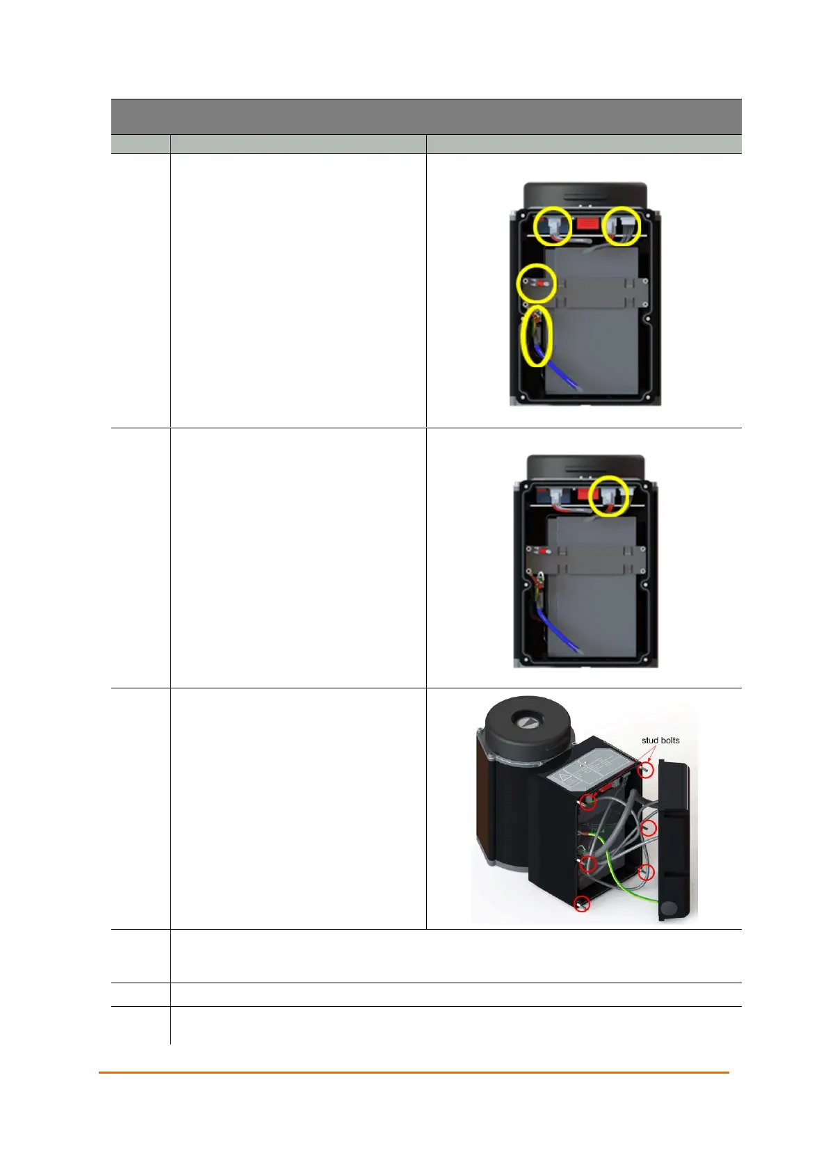
and connect the connectors marked by
yellow circles in the illustration. The two
equal connectors are distinguished by
the color on the cable sleeve. The cable
with the blue sleeve connects to the
cable with the blue sleeve, and the cable
with the black sleeve connects to the
PCB.
Connect the battery connector marked
by a yellow circle in the illustration.
Place the interface back on the actuator.
Make sure no cables get caught on the
sealing surface between the interface
and the actuator. Make sure to not drop
the interface, or to let it hang by the
cables.
Fasten the interface with the six hexagon socket cap nuts by turning them clockwise. Note
the correct sequence for tightening the nuts. See Appendix C Torque and Screw
Recommendations on page 87.
Turn on the power going to the actuators.
Disable service mode from the actuator control system. Make sure that the actuator state
indicator light is green on all actuators that have received a new battery.