8
6600
Fig. 3
B
A
A
A
Bus termination for video signal stabilisa-
tion
The interphone is provided with a “BUS termi-
nation connector” (A-B-C) for video signal sta-
bilisation.
Depending on the connection configuration
(interphones/monitors connected in series or
derived from a distributor), set a jumper on the
connector ABC as described in the note “Bus
termination” in the wiring diagrams section
below.
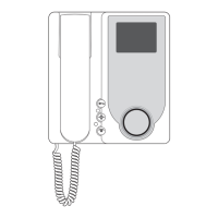
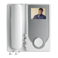
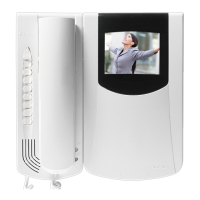
Art. 6621
Art. 6701
Art. 662C
PROGRAMMING
There are three monitor programming modes: assignment of an identifica-
tion code or call code (indispensable), assignment of a secondary identifica-
tion code (for video interphones associated with a master video interphone),
programming of push-buttons for auxiliary services and intercommunicating
calls (when necessary).
Programming must be performed with the system switched on, without
active communication and only after connecting the interphones/video in-
terphones to the system and programming the panels.
Programming the identification code
The identification code is to be programmed by means of an entrance panel
(main- “Master”), present on the installation and already configurated. The
video-interphone is supplied without associated identification code. To
check this, press the “G” push-button and the video-interphone will emit a
triple “Beep”.
Attention: during the interphone/video interphone identification code
programming you have 30 seconds from the moment you enter the
programming in the interphone/video interphone and the moment you
press the call push-button on the panel or you send the code.
Programming phase:
1) Press and hold down “I”.
2) Press and hold down also “H” together with “I”.
3) Wait for nearly 3 seconds until the red led “M” flashes.
4) Now the microprocessor is physically reset.
5) Release both push-buttons “I” and “H”. You have now 5 seconds to
carry out any of the described programmings.
6) Press and hold down the “G” lock push-button.
7)
After nearly 2 seconds the video-interphone emits a high-pitched tone, it
self-starts and gets in communication with the entrance panel.
8) On the entrance panels with push-buttons press the call push-button
corresponding to the video-interphone, on the alphanumeric entrance
panel, on the contrary, enter the call code and press “
”.
9)
If on the installation there is already an interphone / video-interphone with
the same associated identification code, the panel emits a low-pitched tone
and you must repeat the operation from the beginning.
10) If not, the code is associated to the video-interphone and the commu-
nication is terminated.
Programming the secondary identification code
The programming of the secondary identification code is required only when
you want more than a video- interphone to ring at the same time with the
same push-button or call code. The video-interphones which must ring si-
multaneously are associated with the same push-button to the same group.
The “master” interphone / video-interphone is programmed in first place by
means of the previous procedure: “programming the identification code”.
The additional interphones / video-interphones are programmed with the
secondary identification code (see table shown in the wiring diagram section
enclosed with the electronic TWO WIRE ELVOX entrance panels).
A maximum of three audio door entry units plus one group master can be
associated with the same group, without the need for programmer Type
950C or SaveProg.
Programming phase:
1) Press and hold down “I”.
2) Press and hold down also “H” together with “I”.
3) Wait for nearly 3 seconds until the red led “M” flashes.
4) Now the microprocessor is physically reset.
5) Release both push-buttons “I” and “H”
6) Press and hold down the “G” door lock and the “H” self-start push-but-
tons simultaneously.
7) After 2 seconds the video-interphone emits a high-pitched tone and
gets in communication with the entrance panel.
8) Release the door lock “G” and the self-start “G” push-buttons.
9) On the push-buttons entrance panels press the call push-button corre-
sponding to the main (already programmed) interphone / video-inter-
phone, on the alphanumeric entrance panel, on the contrary, enter the
same call code of the “Master” interphone / video-interphone and press
“
”.
10) If on the installation there is already an interphone / video-interphone with
the same associated identification code, the panel emits a low-pitched tone
and you must repeat the operation from the beginning.
11) Once the secondary identification code is associated to the video-inter-
phone, the communication is terminated.
To know the number assigned see table shown in the wiring diagram
section.
EN
 Loading...