36
GB
Video interphone technical specifications
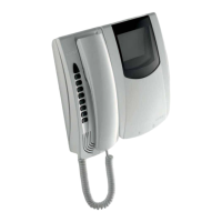
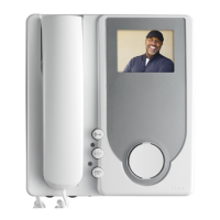
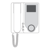
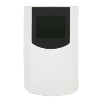
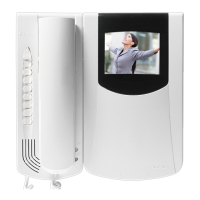
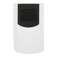
- Interphone in ABS.
- Removable terminal block.
- Electronic circuit on interchangeable cards.
- Operating temperature from 0° to +40° C.
- Electronic ringtone.
- Input for landing calls with different ringtone from entrance panel calls.
- Output for additional ringtone type 860A.
- Supply voltage provided by bus.
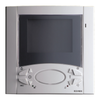
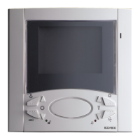
Controls and adjustments
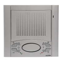
B) Microphone.
C) Loudspeaker.
D) Pair of push-buttons.
2) When the interphone has not self.starter, the push-buttons can be
used to select the tune for calls from a speech unit only. To programme
the tune: hold down 1 of the 2 push-buttons for at least 2 second, then
press the push-buttons repeatedly to select the desired tune.
E) Pair of push-buttons.
1) During conversation, with push-button “I” pressed, press push-buttons
“D” to increase or decrease the volume of the internal voice line.
2) To adjust ringtone volume (with interphone not in conversation): hold
down 1 of the 2 push-buttons “D” for at least 2 second, then press the
push-buttons repeatedly to increase or reduce ringtone volume, or
mute the ringtone. The “D” push-buttons adjusts the chime volume
also during the emission of the internal or external or outdoor call tone.
F) Push-button for auxiliary service, 1st relay of 1st actuator type
69RH.
G) Push-button : to open the lock and terminate any conversation
in progress.
H) Push-button : for self-start of the interphone without being called.
I) Two-channel conversation push-button: after the call and/or
switch-on of the monitor press the pushbutton once to activate the
audio. Pressing it once again the conversation terminates.
The red LED remains lit for the whole conversation dwell.
L) 'Door open' signal: if the green LED lights up, this indicates
that the door is open and if the LED is off, it means all door are closed
(the function is optional according to the type of installation).
M) 'Ringtone mute' LED: if the red LED lights up, this indicates that
the call is disabled (see point "E").
The red LED also remains lit for the entire duration of the conversation,
i.e. while the audio is active.
N) Push-buttons: for sctivation of auxiliary services or intercommunica-
ting calls (in function of the programming)
N.B. On the back of the interphones 6611/AU and 6711/AU is a RESET
push-button for use during programming. In a table version monitor
type 661C/AU the “RESET” push-button is placed under the monitor
base.
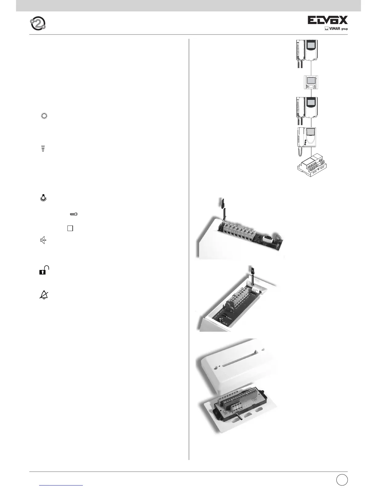
Connection and connector terminal board
+12, CH) Additional ringtone connection.
1, 2) BUS line.
FP, M) Connection for landing call push-button.
VIDEO SIGNAL STABILISATION
On the rear of interphone type 6611/AU and
6711/AU there are some connectors (A-B-C)
for the video signal stabilization.
For the table version interphone type 661C/AU
the video signal stabilization is carried out by
means of a jumper on terminal block A-B-C
present on the stud. This jumper must be used
in installations with several appliances (inter-
phones and monitors) connected in series (Fig.
8.3).
In series configuration displace the jumper (only
in the last set) into “B” position and keep the
jumpers of other interphones or monitors in the
initial position, i.e. “A” (Fig. 8.3).
For other wiring configurations see note: "Bus
termination for ELVOX TWO-WIRE installations"
provided below, in the wiring diagrams section
(Page. 44).
B
A
A
A
Fig. 8.3
type 6601/AU
type 6611/AU
type 6701/AU
type 6711/AU
type 660C/AU
type 661C/AU
Fig. 8.6
Fig. 8.5
Fig. 8,4
 Loading...