16
WIRING DIAGRAM
1
7
6
C1
4
C3
3
SR
D
D1
D3
1
2
4
5
3
C
3451
45312A1
4
A3
1
6
7
3
453
B
12
B1
B3
2
1
5
4
3
A
SR
C
A
6
3451
6
A
C
SD SD
D - Distributor 949B
1435
5431
5
12
6
11
1
4
3
3
5
6
4
1
3
5
6
4
1
V3
13
V1
11
12
M
8
9
6
7
3
4
1
2
5
10
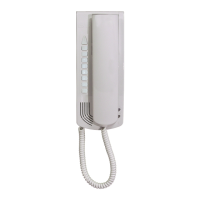
Phone
Art. 8877
Phone
Art. 8877
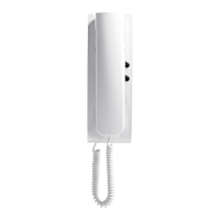
Phone
Art. 6201
Phone
Art. 6201
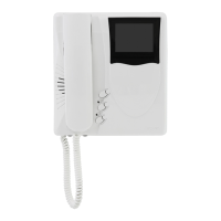
Phone
Art. 6604/AU
Art. 6704/AU
Phone
Art. 887B
Art. 887B/1
D
Phone
Art. 6204
Phone
Art. 887B
Art. 887B/1
DIAGRAM SYMBOLS
A.C. buzzer
A.C. bell
Electric lock
Lamp
Push-button
Switch
Loudspeaker
Amplified microphone
Receiver
A.C. supply from mains
Ground
Section mm
2
0,12 0,25 0,35 0,50 0,75 1,00 1,50 2,50 4,00 6,00
Diameter mm. 0,40 0,58 0,68 0,80 1,00 1,15 1,40 1,80 2,30 2,80
Decimal diameter 4/10 6/10 8/10 10/10 12/10 14/10 18/10
Resistance Ω 100m. 14,00 6,60 4,80 3,50 2,20 1,70 1,14 0,69 0,39 0,28
Conversion table of sections-diameters and relative resistances for 100 m. standard conductors.
Conductors Ø up to 50 m. Ø up to 100 m. Ø up to 200 m.
4-5 0,75 mm
2
1 mm
2
1,5 mm
2
+ - and lock 1 mm
2
1,5 mm
2
2,5 mm
2
Others 0,5 mm
2
0,75 mm
2
1 mm
2
Video Coaxial cable 75 Ohm
MINIMAL CONDUCTOR SECTION (mm
2
)
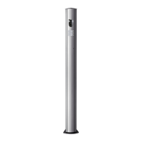
Coaxial cable grip
INTERPHONE RISER WITH FLOOR DISTRIBUTOR ART. 949B (A) AND WITHOUT DISTRIBU-
TOR (B). Ref. diagram si029, si028
The risers shown (Type A or B) must be included in all interphone diagrams given in this
collection.
INTERPHONE
CABLE RISER
INTERPHONE
CABLE RISER
TO POWER SUPPLY
ART. 6941
TO POWER SUPPLY
ART. 6941
A
B
 Loading...