2
ALPHANUMERIC DISPLAY ENTRANCE PANELS: INTRODUCTION
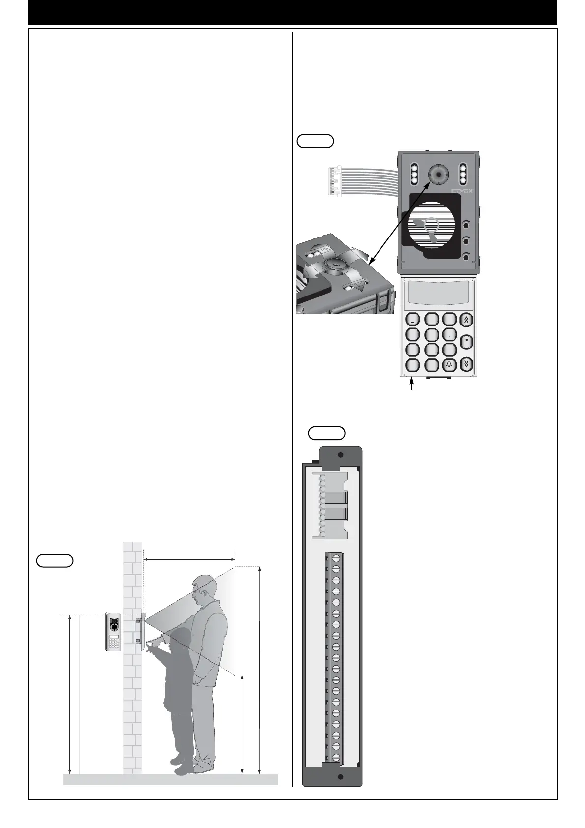
STANDARD MODULES
The standard modules comprise: an electronic unit, a connection termi-
nal block. The electronic unit is equipped with a speech unit, camera on
video versions, wiring for terminal block connections and for connection
of additional modules. The standard modules for video panels in colour
are equipped with a b/w camera with ¼" CCD sensor and fixed 3 mm
lens and white indicator LED. All panels with cameras can be tilted
manually, horizontally or vertically, on removal of the plate.
Example of standard module with camera.
Controls:
1 - Balance
2 – External volume
3 – Internal volume
On the rear of the electronic unit there is a jumper
J1 for the current generator activation/deactiva-
tion (ON = jumper inserted, OFF = jumper cut)
Wiring for ter-
minal block
connection
Manual horizontal and
vertical tilt
Fig. 3
DESCRIPTION
Types 1284 and 1287 comprise respectively an electronic base unit for
the assembling of two models of entrance panels.
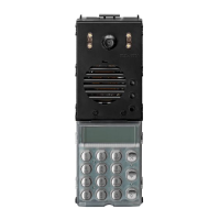
1284 Electronic audio module with electronic name index, alphanume-
ric keypad and display.
1287 Electronic video module with colour camera, electronic name
index, alphanumeric keypad and display.
Both modules (type 1284 and 1287) are equipped with a two line 16
character alphanumeric display and with an electronic name index for
200 users. Each user can be associated with 2 names consisting of 16
characters. An external CCTV type external camera can be connected to
the audio entrance panel after configuring it as video as described in the
paragraph “Hardware programming – Entrance panel programming
modification”. The video colour entrance panels can be used indifferen-
tly either in black and white either in colour installations.
The above mentioned electronic units are to be used with plates
and components of the 1200 series, separately sold.
Each push-button in the electronic units can generate different call codes
with values from 1 to 200. The entrance panels are designed to operate
either alone or with other entrance panels. In any event one must be set
as a Master entrance panel and the others as Slave.
The front of the electronic unit (see Fig. 2) is fitted with the following
adjustments:
1 Voice line balancing control
2 External volume
3 Internal volume
For the panel programming use the entrance panel keypad or the pro-
gramming module type 950B.
The volume adjustment may cause the LARSEN effect (whistle); in this
event operate on trimmer 1 (Balance) or decrease one or both volumes
to avoid the whistle.
INSTALLATION
The assembling and the installation of the electronic units for the 1200
series plates require the following phases:
1- Define the plate for the electronic base unit and the possible additio-
nal plates (see page 3, components).
2- Define the back boxes and the frames for the surface wall-mount or
flush-mount installation (see page 4, accessories).
3- Install the flush-mount or surface wall-mount back boxes with the
upper edge at a height of approx. 1,65 m from the ground (Fig. 1).
4- Fix the rainproof covers to the back boxes.
5- Fix the terminal box of the base module to the module holder frame
of the entrance panel.
6- Connect the terminal block to the system as shown in the wiring dia-
gram.
7- Connect the electronic unit of the base module to the additional pla-
tes, if any, with name-tags.
8- Insert the electronic unit and the additional modules in the module
holder frames of the entrance panels.
9- Insert the microphone of the electronic base unit in the module hol-
der frame of the entrance panel (Fig. 5, Part 1).
10- Program the entrance panel.
11- Insert the external plate of the electronic unit in the module holder
frame and the additional entrance panels in the remaining module
holder frames.
12-Close the panel.
1,65m
2,04m
1,04m
1m
Fig. 1
3
2
1
123
4
5
6
7
8
9
0
ABC DEF
GHI
JKL
MNO
PQRS
TUV
WXYZ
+
R
CANC
Electronic unit
Fig. 2
V13458V1M1V2SR+ICHVL4F1F2+L 6
CN1
ELVOX CS2375 211004
M
V13458V1M1V2SR+ICHVL4F1F2+L 6 M
TERMINAL BLOCK
Terminal Description
+I Monitor shutdown control terminal.
S
Electric lock activation control terminal.
F2 Auxiliary function 2 activation control
terminal.
F1 Auxiliary function 1 activation control
terminal.
+L Panel active terminal.
CH Call signal activation control terminal.
8 Terminal for voice signal in building
complex.
6 Terminal for digital signal in building
complex.
V2 Video signal terminal.
M Video signal earth terminal.
V1 Video signal input terminal.
5 +13.5Vdc supply voltage terminal.
4 Negative supply voltage terminal.
3 Terminal for voice signal to interpho-
ne/monitor cable riser.
1 Terminal for digital signal to interpho-
ne/monitor cable riser.
V Video signal output terminal.
M Video signal earth terminal.
VL Terminal for use (option) with “sel-
fprotected” system (see page 13,
point 26. See Variations on Page 35.
 Loading...