5
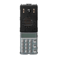
ENTRANCE PANEL WITH TRADITIONAL PUSH-BUTTONS: INTALLATION
Fig. 6
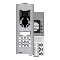
Fig. 7
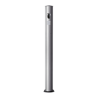
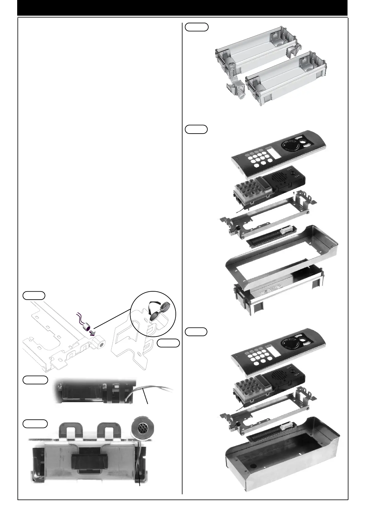
Fig. 8
FLUSH-MOUNTED ENTRANCE PANEL INSTALLATION WITH RAIN-
PROOF COVERS.
Assembly of flush-mounted entrance panel requires the use of the flush-
mounted back boxes type 9092, 9093 respectively for 2 or 3 electronic
modules mounted vertically (Fig. 4A and 4B).
If the entrance panel uses more than one flush-mounted back box, the
rainproof covers must also be used (see plates WITH ALPHANUMERIC
DISPLAY: accessories on page 4, series 1Pxx), according to the number
of modules fitted vertically or horizontally.
Installation:
-
If the installation requires a combination of several back boxes, use the
hooks supplied with the back boxes to secure them together (Fig. 8).
- Install the back box with the upper edge at a height of approx. 1,65 m
from the ground (Fig. 1).
- Fix the terminal block of the electronic unit under the module holder
frame by means of the screws supplied (Fig. 7).
- Fix the rainproof cover to the flush-mounted back box using the
screws supplied (Fig. 7).
- Fix the module holder frames to the frames and the back boxes (Fig. 7).
- Connect the terminal box of the electronic unit to the system.
- Connect the electronic unit to the terminal block by means of the
wiring on the upper section.
- Connect the additional modules, if any, and insert them.
- Insert the electronic unit.
- Insert the microphone in the lower right section of the module holder
frame (Fig. 5).
Pay attention that the microphone cables are inserted in the external
slot of the electronic module (Fig. 5A, 5B).
- Close the entrance panel, attaching the plate first from the upper sec-
tion and then securing the lower section by means of the special key
on the head section.
- Perform the programming phases (page 6).
SURFACE WALL-MOUNTED ENTRANCE PANEL INSTALLATION
Assembly of the surface wall-mounted entrance panel requires the use
of the back boxes series 1Exx.
Installation:
- Fix the electronic unit terminal block under the module holder frame
by using the screw provided (Fig. 8).
- Fix the module holder frames to the frames and back boxes (Fig. 8).
- Connect the terminal block of the electronic unit to the system.
- Connect the electronic unit to the terminal block by means of the
cable present on the upper section (Fig. 2).
- Connect the additional modules, if any, and insert them.
- Insert the electronic unit.
- Insert the microphone in the right lower section of the module holder
frame (Fig. 5).
Pay attention that the microphone cables are inserted in the external slot
of the electronic module (Fig. 5A, 5B).
- Insert the module plates in the module holder frames (Fig. 8).
- Close the entrance panel, attaching the plate first from the upper sec-
tion and then securing the lower section by means of the special key
on the head section.
- Perform the programming phases (Pag. 6)
Fig. 5
part. 1
Fig. 5A
Fig. 5B
Microphone cable
Electronic unit with module holder frame
Electronic unit without module holder frame
Microphone cable
 Loading...