I
7
GB
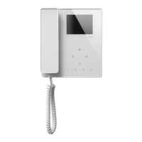
INSTALLATION OF MONITOR AND TELEPHONE
Fig. 8 - Embed 3 module back box Art. 7149 so that
it is flush-mounted on the wall about 1.45 m
from the ground.
Fig. 9 - Attach mounting bracket Art. 6146 using the
4 screws provided and keeping flush-moun-
ted back box at the right hand side of the
plate. Fix the connecting circuit (provided
with the monitor) on the plastic seat provi-
ded with the plate.
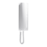
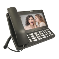
Fig. 10 - Carry out the connection of the installation
to the monitor connection circuit. Insert the
telephone cable (provided) in the connector
in the socket on the back of multi-function
telephone Art. 3562. Connect the other end
of the cord to the telephone line from the te-
lephone switchboard (Art. 3528/N-3528) by
inserting the plug in the socket on acces-
sory Art. 3560 (detail A).
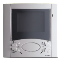
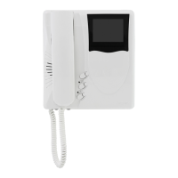
Fig. 11
- Attach the telephone to the mounting brac-
ket by hanging it over the hooks and pushing
it down until it is locked in place. Insert mo-
nitor cable in the connector marked “CN1”
on the connecting circuit board (detail B). Fi-
nally mount the monitor by hanging it over
the hooks and pushing it down until it is loc-
ked in place. To detach the telephone or mo-
nitor from the mounting bracket, prise open
the safety tab with a screwdriver and detach
the unit by pushing it up (in the opposite di-
rection to that indicated by arrows 1 and 2).
N.B.: Do not use the cable supplied with the
con-
necting circuit board
.
MONTAGGIO MONITOR CON TELEFONO
Fig. 8- Murare la scatola da incasso a 3 moduli ad
un’altezza di circa m.1,45 dal pavimento.
Fig. 9- Fissare la staffa Art. 6146 con le 4 viti a cor-
redo, tenendo la scatola di incasso a destra
della piastra. Fissare il circuito di intercon-
nessione fornito con il monitor nell’alloggio
in plastica fornito con la piastra.
Fig. 10- Eseguire i collegamenti dell’impianto al cir-
cuito di interconnessione del monitor. Inse-
rire il cablaggio telefonico in dotazione nel
connettore posto sul retro del telefono mul-
tifunzione Art. 3562. Dal lato opposto del ca-
vetto collegare il plug alla linea telefonica
proveniente dal centralino telefonico tramite
l’apposito accessorio Art. 3560 (particolare
A).
Fig. 11- Inserire il telefono sulla staffa appoggiandolo
nelle apposite sedi e tirandolo verso il basso
fino al suo completo bloccaggio. Inserire il
cablaggio del monitor nell’apposito connet-
tore denominato “CN1” posto nel circuito di
interconnessione (particolare B).
Inserire infine il monitor appogiandolo nelle
apposite sedi e tirandolo verso il basso fino
al suo completo bloccaggio. Per estrarre il
telefono o il monitor dalla piastra di aggan-
cio, agire con un cacciavite sulla linguetta di
sicurezza ed estrarli seguendo il senso in-
verso delle frecce 1-2.
N.B. Il cablaggio in dotazione al circuito di inter-
connessione non va utilizzato.

 Loading...