Do you have a question about the Elvox Vimar K40515.R and is the answer not in the manual?
Guidance on optimal installation height and avoiding light glare for clear display visibility.
Installation must be performed by qualified personnel following electrical installation regulations.
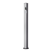
Details on surface mounting (Vimar 71303) and semi-flush mounting (40590).
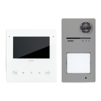
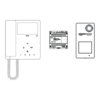
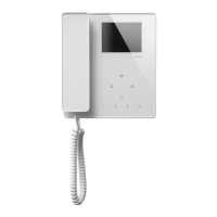
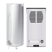
Overview of various installation possibilities including surface, flush, and desktop mounting.
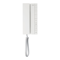
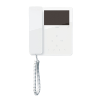
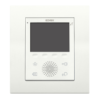
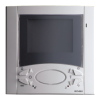
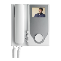
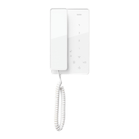
General identification of device buttons and their default roles.
Details on the device's display, touch-screen, and Wi-Fi capabilities.
Information on power consumption, operating environment, and protection ratings.
Identification and description of components visible on the device's front panel.
Explanation of the function and behavior of the white backlit indicator LEDs.
Details on the audio frequency function for hearing aid users (Teleloop).
Explanation of default functions for each button, including call, self-start, and door opening.
Description of terminals and their functions for bus, power, and inputs/outputs.
Explanation of DIP switch table and jumper settings for bus termination and relay control.
Instructions for setting the BUS POWER switch for different power supply configurations.
Details on power supply via bus, auxiliary, USB, and energy saving mode operations.
Methods for updating firmware using FWUpdate via PC or the View Wireless App.
Explanation of LED signals indicating the status of the firmware update process.
Instructions for removing the camera lens protective film and cleaning the lens.
Statement confirming all installations must adhere to the Due Fili Plus standard.
Steps to configure the system using the View Wireless application.
Procedure for pairing the device with a smartphone using Bluetooth provisioning.
Explanation of how to operate the locking mechanism for the device.
Identification of the fixing slots and mounting points on the device.
Step-by-step guide for mounting the glass panel onto the device.
Instructions for mounting the push buttons onto the device.
Procedure for safely disassembling and removing the glass panel.
Instructions for disassembling and removing the push buttons.
Guide to installing the accessory 40177, a rain-proof frame for the outdoor station.
Identification and description of internal components and connection points.
Details on terminal blocks, configuration jumpers for NO/NC contacts, and USB connector.
Explanation of LED signals for call in progress, active communication, and lock operation.
Interpretation of LED signals related to access control, bus status, and communication errors.
Detailed technical specifications for the 40110 power supply unit.
Information on installation requirements and safety symbols for the power supply.
Diagram illustrating the wiring for a one-family video door entry system.
Diagram illustrating the wiring for a two-family video door entry system.
Details on connecting an additional CCTV camera to the outdoor station 40170.
Information for users regarding the proper disposal of the product as WEEE.
Vimar S.p.A.'s commitment to personal data protection in accordance with EU Regulation 2016/679.
List of directives and standards the product complies with (RED, RoHS, EN, REACH).
| Brand | Elvox |
|---|---|
| Model | Vimar K40515.R |
| Category | Intercom System |
| Language | English |