EM TEST UCS 500 Series
Operating Manual V 3.05 26 / 57
9.4. Coupling decoupling network
The decoupling part of the coupling network has to:
- filter the interference pulses in the direction to the power supply;
- protect other systems that are connected to the same power supply and
- realize a high impedance of the power supply, e.g. battery supply.
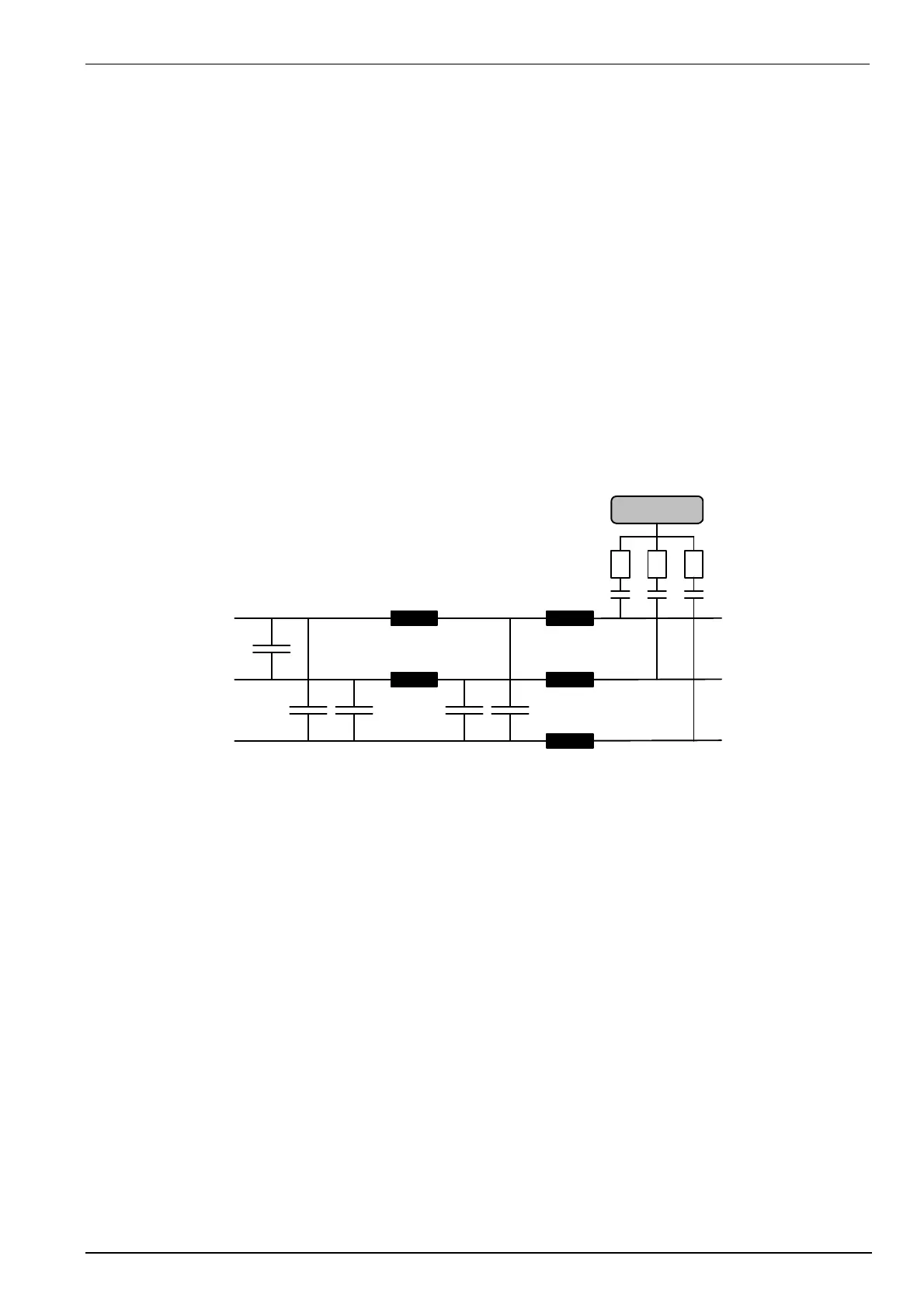
9.4.1. Coupling/decoupling network for ac/dc power lines
The coupling network has to couple the interference pulses to the lines of a power supply system (AC or DC). As
coupling devices capacitors of sufficient strength and bandwidth shall be used according to IEC 61000-4-4.
- Normal Mode
Line => GND
Neutral => GND
- Common Mode
Line + Neutral => GND
- Protective Earth PE
The PE of the EUT is decoupled from the power supply side by a choke. The
interference source is coupled directly to the PE of the EUT.
The decoupling part of the coupling network has two purposes:
- to filter the interference pulses in the direction of the power supply side;
- to protect other systems that are connected to the same power supply and
- to realize a high impedance of the power supply, e.g. battery supply.
Coupling network acc. to IEC 61000-4-4
Ck
The coupling on signal lines can usually not be effected capacitively without interfering with the signal flow. It is
often impossible to contact the required circuit (direct), e. g. coaxial or shielded cables. In this case the coupling
is realized with the capacitive coupling clamp. The interference simulator can be connected on both sides of the
coupling clamp.
Attention:
The actual published IEC 61000-4-4 (1995) requires all lines to be tested individually.
The new draft revision IEC 61000-4-4 edition 2 (2004) requires the Common Mode coupling only. This means all
lines simultaneously to ground.
 Loading...