Do you have a question about the EM TEST UCS 500Mx and is the answer not in the manual?
Introduces the UCS 500Mx as an ultra-compact simulator and its system modules for immunity tests.
Lists the key EMC standards covered by the UCS500Mx, including IEC 61000-4 series.
Details the different UCS models available, including standard and special versions.
Enumerate the specific EMC standards that the UCS 500M is equipped to cover for testing.
Explains the operational modes and menu navigation for voltage dip testing.
Covers required test setups and accessories like transformers for voltage dip tests.
Details the ESD generator, its setup, and important testing points according to the standard.
Provides the CE conformity declaration for the UCS 500M product line.
Lists and compares specifications for standard and special UCS models like M4, M6, M6A, and S1.
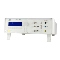
Describes the functions of the controls and indicators visible on the front panel of the UCS 500M.
Details the various input, output, and synchronization connectors located on the rear panel.
Explains the HV output for surge pulses and monitoring outputs for voltage and current.
Describes the ventilation system and the warning lamp functionality for safety indications.
Details the RS 232 serial and IEEE 488 parallel interfaces for communication and control.
Explains the FAIL 1 and FAIL 2 inputs for test stop and pause control based on EUT status.
Describes how to navigate the menu system using function keys, knob, and cursor keys.
Provides a hierarchical overview of the simulator's menu structure, from Level 0 to Level 4.
Details the primary functions available in the main menu: Burst, Surge, Power Fail, ESD, and Service.
Outlines the available service functions like addresses, setup, standard level changes, and status display.
Explains setup options for language, LCD, interfaces, beep, timers, voltage, and magnetic field factors.
Lists and identifies the main boards and transformers within the control unit section.
Describes the components of the high voltage and coupling/decoupling units.
Details test levels, waveform parameters like rise time, duration, and impedance for EFT burst testing.
Describes available test routines and output specifications for EFT burst testing.
Specifies test levels, waveform parameters, and repetition rates for Surge immunity testing.
Details output configurations, coupling networks, and available test routines for Surge immunity.
Covers EUT supply parameters, mains frequency, inrush current, protection, and trigger settings.
Lists test routines for power fail events and magnetic field testing requirements.
Details air and contact discharge modes, parameters like voltage, capacitor, and resistor for ESD testing.
Provides general specifications including mains supply, power consumption, safety features, interfaces, dimensions, and weight.
Highlights specific differences in warning lamps, synchronization, and inrush current for the upgraded UCS 500.
States the generator is maintenance-free and recommends test setup guidelines for safety.
Describes the factory calibration process, traceability, and the importance of calibration adapters.
Lists the essential components included in the basic delivery group of the UCS 500M.
Details optional accessories for Burst, Surge, Power Fail, Magnetic field, and ESD testing.
Introduces the Burst menu, offering Quick Start, Standard, and User test routines for EFT burst testing.
Guides on using the Quick Start function for easy and fast online operation of burst tests.
Lists preprogrammed standard test routines for EFT Burst based on IEC and EN standards.
Explains how to use the manual standard routine for flexible burst testing with online parameter changes.
Describes how users can program, save, and recall their specific test routines for burst testing.
Details the function for sweeping frequencies within a single burst, with parameter limitations.
Explains frequency sweeps with constant pulse duration, including parameter limitations.
Discusses the semiconductor discharge switch and its limitations for burst generation.
Shows maximum test levels for Burst based on the number of couplings for different UCS models.
Explains the purpose of the decoupling part of the network: filtering and impedance.
Describes the coupling network for AC/DC power lines, including normal and common mode coupling.
Details the use of the capacitive coupling clamp, its impedance, and placement for testing.
Provides guidelines for setting up the burst test generator and coupling network, including grounding.
Lists the available surge test routines: Quick Start, Standard, User, Pulse Magnetic Field, Ring Wave, and Current Limiter setup.
Guides on using the Quick Start function for easy surge testing with automatic recall of last settings.
Details the selection of standard surge test routines based on IEC 61000-4-5 levels and EN 61000-6 standards.
Explains the process of iterating surge tests synchronized to phase angle and voltage, and line-to-earth testing.
Describes how to adjust surge parameters online during testing using cursor and knob controls.
Explains user-defined routines for surge tests: polarity change, coupling change, voltage change, phase angle change.
Details the operation of the pulse magnetic field test, similar to standard surge routines, and required setup.
Refers to the RWG 500 modules manual for Ring Wave application details.
Explains how to set the maximum allowable surge current for EUT protection.
Mentions the semiconductor switch used for surge pulse generation.
Describes coupling methods for power supply lines and I/O lines using integrated or external networks.
Lists the main Power Fail test routines: Quick Start, Standard, User, and Magnetic Field.
Guides on using Quick Start for fast power fail testing, including parameter explanations.
Details standard routines for AC power supply mains, including dips and voltage variations.
Lists standard routines for DC power supply systems based on IEC 61000-4-29.
Explains generic standard routines for EN 61000-6-1 and EN 61000-6-2.
Details dip levels for DC power supply systems according to IEC 61000-4-29.
Describes how to change power fail parameters online during testing using manual routines.
Explains user-defined routines for voltage variation, phase angle change, and duration change.
Describes different power fail test modes (interruptions, dips) and channel configurations (PF1, PF2).
Details the electronic power switches, input channels, and their connection requirements.
Explains high impedance interruptions where the EUT discharges internally.
Describes low impedance interruptions involving short-circuiting channel PF2.
Details how voltage dips and variations are achieved using variacs and channel switching.
Discusses grounding and measurement considerations for DC power supply operation.
Explains the use of the V4780 transformer to generate voltage dips and interruptions according to standards.
Lists V4780 device models and details the control mechanism for the V4780 S2.
Provides technical data for V4780 models, including input, output, power, and dimensions.
Shows setup diagrams for connecting the V4780 transformer to the simulator and EUT.
Explains the use of the MV 2616 motor variac for simulating power supply failures.
Details how the motor variac is used for voltage variation functions programmed via simulator or software.
Lists technical specifications for the MV 2616 variac, including input voltage, output, control, and dimensions.
Describes the test setup involving a variac, antenna, and transformer for magnetic field testing.
Introduces the ESD operation, covering Quick Start and Standard test routines.
Details the parameters available in the ESD Quick Start mode, including voltage and trigger settings.
Explains parameters for standard ESD test routines like mode (Air/Contact) and trigger type.
Provides crucial guidelines for test table, ground reference plane, and generator placement for reproducible ESD tests.
Describes direct and indirect discharge applications to EUT parts and surfaces.
Presents a matrix of test levels for contact and air discharges as per IEC 61000-4-2.
Explains the connecting cable, ON/OFF key, exchangeable discharge tips, and polarity reversal.
Lists manufacturer, product name, and declared conformity with Low Voltage and EMC Directives.
Shows a general block diagram of the UCS 500 M, illustrating major units and their connections.
Details the main control connections between various boards and modules within the UCS 500 M.
Illustrates the main high voltage connections for surge, burst, and ESD pulses within the UCS 500 M.