EM TEST UCS 500 Series
Operating Manual V 3.05 5 / 57
3. Operating Functions
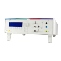
3.1. Front view
1 Display
2 "Test On"
3 Function keys "F1..F7
4 Knob (Inc / Dec
5 Cursor keys "←" and "→"
6 Exit
7 Escape
8 CRO U (surge
9 CRO I (surge
10 CRO trigger output ↑ 5V
11 HV pulse Burst output 50 Ω
12 Ground reference
13 Coupling ( burst, surge and ESD
14 Channel PF1 and PF2
15 EUT test supply
1 Display
All functions and parameters are displayed (8 lines with max. 40 characters).
2 Test On
By pressing the key "Test On" the test procedure is initiated with the preselected parameters. The red LED indicates the
trigger of a burst event.
3 Function keys "F1 .. F7
Parameters and functions, displayed in the lowest line, can be selected with the related function key.
4 Knob (Inc / Dec
The knob increments or decrements test parameters with a numeric value or selects from a list of parameters.
5 Cursor keys
Parameters and functions can be changed on-line. The selection of these parameters is realized with the cursor moving to
the left or to the right.
6 Exit
Pressing of the Exit function will cause a reset of the firmware. This is only possible if no test routine is running.
7 ESC
When pressing the ESC button the user moves back one page in the menu.
8 CRO U (surge)
At the BNC output the voltage pulse (surge) of the generator can be measured. The max. level is 10V
9 CRO I (surge
At the BNC output the current pulse (surge) of the generator can be measured. The max. level is 10V
10 BNC - CRO Trigger
At the BNC output the generator trigger can be checked, e.g. the burst duration, the burst repetition rate and the spike
frequency (+15 V rectangular). This output can be generally used as oscilloscope trigger output and is synchronous to the
following events
- Burst and surge release
- Voltage dip or interruption, start of the event
- ESD contact discharge
11 HV pulse output 50
External coupling devices such as the capacitive coupling clamp and the 3-phase coupling network are connected to the
coaxial 50 ohm output. Also the calibration of the generator is handled at this output
12 Ground reference
During test or calibration procedure the burst generator must be grounded to the reference ground plane
13 Coupling mode
The actual coupling mode is indicated by LED
14 Channel PF1/PF2
This LED indicates the channel mode during the power fail test.
15 EUT test supply
For single-phase EUT the coupling/decoupling network is part of the generator. The EUT is powered via the safety banana
plugs at the front panel of the simulator
 Loading...