EM TEST UCS 500 Series
Operating Manual V 3.05 35 / 57
10.2. Surge pulse generation
Discharge switch:
The discharge switch is a highly reproducible semiconductor switch.
10.3. Coupling decoupling network
The coupling network has to couple the interference pulses to the lines of a power supply system (AC or DC).
Capacitive coupling is the specified coupling mode for surge testing.
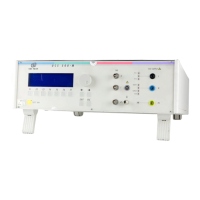
10.3.1. Coupling to ac/dc power supply lines
The surge generator UCS 500 has an integrated coupling network in accordance with IEC 61000-4-5. It must be
possible to test with different coupling modes:
Line
→ GND or (source impedance is 12Ω)
Neutral
→ GND or (source impedance is 12Ω)
L + N
→ GND or (source impedance is 12Ω)
Line
→ Neutral (source impedance is 2Ω)
Coupling Line to Line Coupling Line to Earth
The release of the surge pulses is mostly related to a certain phase angle.
The surge pulses are synchronized to the input signal at the rear Sync-connector.
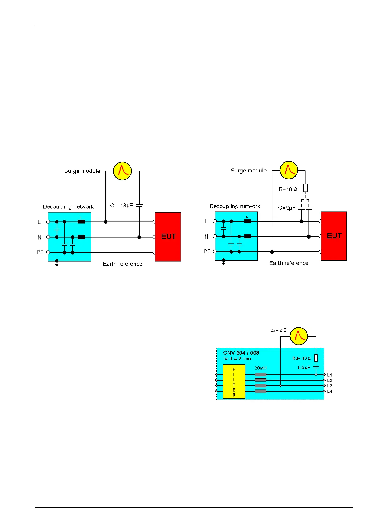
10.3.2. Coupling to I / O lines
The coupling to I/O lines is generally realized with other
coupling networks than for power supply lines. The loading
of the I/O lines with big coupling capacitors is mostly not
possible. The data transmission may be disturbed.
For coupling to I/O lines special couplers as per IEC 61000-
4-5 are available, such as the CNV 504 and the CNV 508
for four respectively for eight wire systems.
10.4. Test set-up
According to the specifications of IEC 61000-4-5, the surge generator has a source impedance of 12ohm when
the simulator is coupled between the lines and protective earth.
This will activate fault current detectors or protectors which may be installed in the laboratory.
Therefore it is important
- not to disconnect the surge simulator form protective earth (power cable)
- to have an installation where the simulator is connected via its ground reference connector to earth
 Loading...