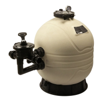
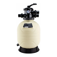
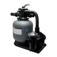
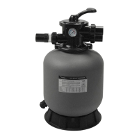
FILTER MAX SERIES
PARTS FOR FILTER MAX FILTER
MODEL: MFS17 / MFS20 / MFS24 / MFS27A / MFS27 /
MFS31A / MFS31 / MFS35
1-4
4-4
EMF I1603 0555
Your Emaux “Filter Max” Filter is a high performance corrosion-proof filter that has superior flow characteristics that is with the
ease of operation. Everything is made simple from installation, operation to the maintenance of the filter. Your “Filter Max”
filter will be your pool filtration partner that provides clear water with the least maintenance hassle and care.
WARNING: BEFORE INSTALLATION BE SURE TO READ ALL INSTRUCTIONS AND WARNINGS
CAREFULLY. KEEP THIS USER MANUAL FOR FUTURE REFERENCE.
HOW IT WORKS
The Filter uses special sand to remove dirt particles from pool water. Filter sand is loaded into the filter tank to
act as the filtration media. The pool water which contains dirt particles is pumped through your piping system to
the filter via the filter control valve. As pool water passes through the filter, dirt particles will be caught by the
sand bed and filtered out. The cleaned pool water is returned from the bottom of the Filter Tank, through the
control valve and back to the pool through your piping system. The entire process is continuous and automatic.
It is this process that provides the filtration and circulation of water in your pool.
With the filtration process, dirt will accumulate and becomes saturated in the filter tank. Pressure in the tank will
increase and the resistance of water flow will occur. This means it is time to clean (backwash) your filter.
Another indication to know when to clean (backwash) the filter is by checking the pressure gauge reading.
Backwash operation should be performed when the pressure increases by 10psi above the pressure when it was
clean. Typically a clean filter will run at 10 to 15psi, so take note of the pressure gauge reading when the filter
was installed. When the pressure reaches approximately 20 to 25psi or 50% increase from the clean reading,
proceed to the Backwash operation.
WARNING: turn off the pump before switching the control valve handle.
To perform the Backwash operation, position the handle on the control valve to “Backwash”, the water flow is
automatically reversed through the filter so the water is directed from the bottom of the tank, up through the
sand, flushing the trapped dirt and debris
out of the waste line. The duration of the backwash operation will depends on how dirty your filter is. Check the
sight glass to see when the water becomes clear. It is recommended that the backwash should be at least 2
minutes long.
Once the backwash operation had been completed, the filter should go through the process of “Rinse” and
then back to “Filter”. To perform the different operations, position the handle on the control valve as indicated.
MFS17
MFS27 , MFS31A, MFS31, MFS35
, MFS20 , MFS24 , MFS27A
1. Place on tank
opening.
2. Add water to
cover laterals
and add sand.
INSTALLATION
Installation had been made simple, the only tools needed is a
screwdriver and pipe sealant for plastic.
The filter should be installed as close to the pool as possible, but
keep a distance of at least 5 feet (1.5m). Locate the Filter on rigid,
level surface, preferably in a dry, shaded, and well-ventilated
area. Prior to installation give consideration to the following:
Position of suction, return, and waste connections. Access for
backwashing operation and servicing; protection from sun, rain,
splashing, etc; Drainage of filter room; Ventilation and protection
of the motor.
1)Fill the tank with water to the level that covers the laterals
(crepinas), or about 1/3 of the tank height is recommended.
This will avoid damages to the laterals (crepinas) by the force
of the sand when pouring into the filter.
80g印尼蓝
普通印刷
2016.03
1 : 1
420X297(mm)
EMFI16030555
PANTONE Process Black C
材 料
工 艺
日 期
EMAUX MFS系列 侧出麦仕胶缸 英文说明书
名 称
版 本 编 号
规 格
比 例
颜 色
产品负责人
更改日期
更改内容
零部件清单
版本
制图/设计
D
意万仕(中山)泳池设备有限公司
EM AU X Z h o n gS h a n ) S wi m m i n g Po o l E qu i p m en t Co ., L t d(
审核
批准