2-4
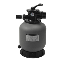
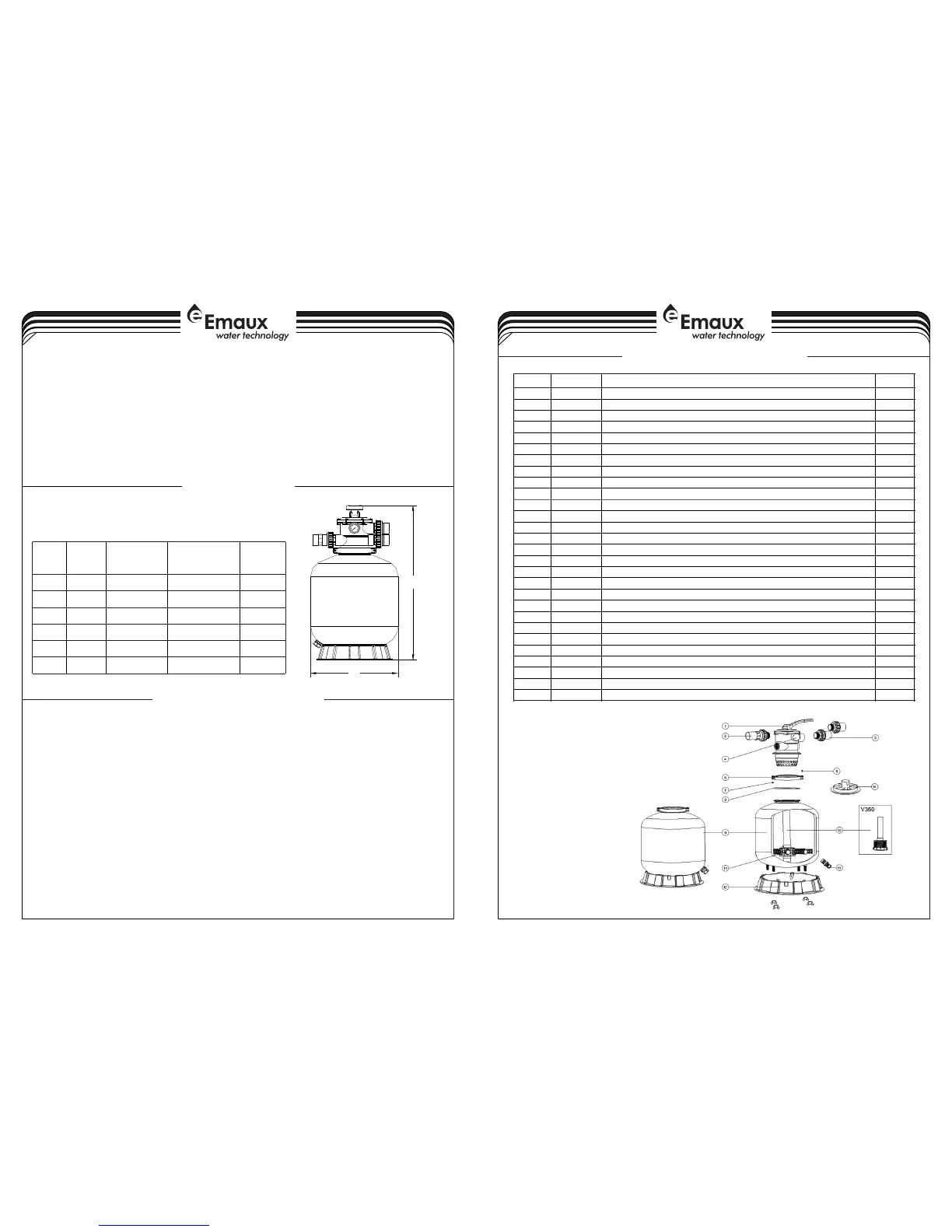
MAIN DIMENSION
REPLACEMENT PARTS OF FILTER
3-4
1) Make sure the correct amount of filter media sand is located in the tank and all connections have been
connected and secured.
2) Depress control valve handle and rotate to BACKWASH position. (To prevent damage to control valve seal,
always depress handle before turning.)
3) Prime and start pump according to pump instructions (be sure all suction and return lines are open), allowing the
filter tank to fill with water. Once water is flowing out of the waste line, run the pump for at least 1 minute. The initial
back-washing of the filter is recommended to remove any impurities or fine sand particles in the sand media.
4) Turn pump off and set valve to RINSE position. Start pump and operate until water in sight glass is clear, about 1/2
to 1 minute. Turn pump off and set valve to FILTER position and restart pump. The filter is now operating in the
normal filter mode, filtering dirt particles from the pool water.
5) Adjust pool suction and return valves to achieve desired flow. Check system and filter for water leaks and tighten
connections, bolts, nuts, as required.
6) Note the initial pressure gauge reading when the filter is clean. (It will vary from pool to pool depending upon the
pump and general piping system.) As the filter removes dirt and impurities from the pool water, the accumulation
of dirt in the filter will cause the pressure to rise and diminish the water flow. When the pressure gauge reading is
1.5 bar, higher than the initial "clean" pressure you noted, it is time to backwash the filter (see BACKWASH under
filter and control valve functions).
INSTALL/START-UP OF FILTER
B
A
DIMENSION TABLE
A
B
Model
High
Diameter
mm
mm
Inch
Valve Port Size
Sand
kg
726P350
350
20
1.5"
757P400 400
35
1.5"
814P450 449
45
1.5"
845P500 527
85
1.5"
950P650 627
145
1.5"
1020P700 703
210
1.5"
3) Assemble filter control valve into the filter tank.
a) Insert filter control valve (with O'ring in place) into the tank neck, taking care that the center pipe slips into
the hole in the bottom of the valve.
b) Place two plastic clamps around valve flange and tank flange and tighten just enough so that the valve
may be rotated on tank for final positioning.
c) Carefully screw pressure gauge (with O'ring in place) into tapped hole in valve body. Do not over-tighten.
d) Connect pump to control valve opening marked PUMP. After connections are made, tighten valve flange
clamps with screwdriver, tapping around clamp with screwdriver handle to help seat valve flange clamp.
4) Make return to pool pipe connection to control valve opening marked RETURN and complete other
necessary plumbing connections, suction lines to pump, waste, etc.
5) Make electrical connections to pump per pump instructions.
6) To prevent water leakage, make sure all pipe connections are tight.
NOTE: During initial clean-up of the pool water it may be necessary to backwash frequently due to the unusually
heavy initial dirt load in the water.
Notes:
11* 01172007 is laterals (115mm) for P350/ P400/ P450
11* 01172008 is laterals (126mm) for P500/ P650/ P700
 Loading...