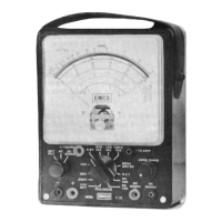
MODEL V-20
Please add the following to your OPERATING MANUAL. On page 2, after the title OPERATING INSTRUCTIONS,
insert the following paragraph:
Before proceeding, remove the instrument from the cabinet. Insert a large flashlight battery. D-Cell, into the battery
bracket mounted on the wall of the bakelite case The Positive terminal of the battery is to face up towards the top of the
case. Now insert the four penlight batteries, AA-cells, into the battery bracket mounted on the meter. Adjacent batteries
are to be inserted in opposite directions. Thus, the battery closest to the large 2 Megohm resistors, is inserted with the
positive terminal up towards the top of the panel. The next battery is inserted with the positive terminal down. The third
battery is inserted into the bracket with the positive terminal up while the battery located furthest from the resistors, is
inserted with the positive terminal down.
Replace and secure the VOM panel in its cabinet.
If you have a kit please make the following changes:
Page 6, Fig. 1
A rectangular pot is shown on right end of resistor board, redraw it so that it is at the left end.
PAGE, 7 STEP 2, CHANGE WIRE LENGTH FROM 1-1/2” TO 1-3/4”
PAGE 13 STEP 8, CAPACITOR LEAD LENGTH SHOULD BE OUT TO 3/4"
PLEASE NOTE:
R 12 AND R 14 (part no. 11035) BOTH 7.5 Meg. RESISTORS WHICH ARE USED IN SERIES TO MAKE
15 MEGOHM 1% ARE NOW ANY TWO VALUES TOTALING 15 MEGOHMS 1%. THEY ARE PACKED IN A
SMALL ENVELOPE MARKED R12-R14 PART NO. 11035.
I.E. 2335
ADMENDMENT
19
 Loading...