Do you have a question about the Emco V-20 and is the answer not in the manual?
Lists the various ranges for DC Voltage, AC Voltage, DC Current, and Output Voltage.
Specifies decibel ranges and calibration reference.
Lists resistance ranges and their corresponding center scale values.
Provides physical size and weight of the instrument.
Explains how to adjust the meter pointer to zero before taking readings.
Step-by-step instructions for measuring DC voltage.
Instructions for measuring AC voltage, with differences from DC.
Instructions for measuring DC current, including cautions.
Step-by-step instructions for measuring resistance.
Instructions for measuring output voltage, noting capacitor effects.
Explains using a chart to correct output voltage readings at low frequencies.
Instructions for decibel measurements and reading the scale.
Provides conversion charts for capacitance based on voltage readings.
Provides conversion chart for inductance based on voltage readings.
Step-by-step instructions for performing high resistance measurements.
Provides conversion chart for resistance based on voltage readings.
Explains the circuit theory for DC voltage measurements.
Explains the circuit theory for AC voltage measurements.
Explains the circuit theory for resistance measurements.
Explains the circuit theory for DC current measurements.
Explains the circuit theory for output voltage measurements.
Explains the circuit theory for decibel measurements.
Instructions for replacing the instrument's batteries.
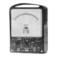
The EMCO V-20 VOM (Volt-Ohm-Milliammeter) is a high-quality, 31-range multimeter designed for accurate and versatile electrical measurements. Its core function is to measure DC voltage, AC voltage, DC current, and resistance, with additional capabilities for output voltage and decibel measurements.
The V-20 utilizes a sensitive 50 microampere, D'Arsonval meter movement, providing a high sensitivity of 20,000 ohms per volt on DC and 1000 ohms per volt on AC. This high sensitivity is crucial for minimizing the impact on the circuit under test, ensuring more accurate readings. A notable feature is the inclusion of factory-adjusted wire-wound potentiometers, which compensate for the individual characteristics of the rectifier, ensuring standardized accuracy across various measurement ranges.
For DC voltage measurements, the V-20 can measure from 0.1 volts (on the 2.5 volt scale) up to 5000 volts, thanks to an internal high voltage multiplier. AC voltage measurements cover the same range, from 0.1 volts to 5000 volts. DC current measurements are possible from 1 microampere (on the 50 microampere scale) up to 10 amperes. Resistance measurements extend to 20 megohms.
An added convenience is the output voltage measurement feature, which includes an internal blocking capacitor that can be switched in when measuring output signal voltage in circuits where DC is present. This allows for accurate AC voltage readings without interference from any DC component. The instrument also offers decibel (DB) measurements, calibrated for use across a 500 ohm line.
The V-20 is designed for ease of use, featuring a large 4-1/2" meter face that facilitates easy reading and reduces the probability of error. The instrument is housed in a rugged, polished, high-impact bakelite case with a genuine leather carrying handle, making it durable for daily use in various environments, including television, f-m, and a-m servicing and manufacturing.
Before taking any measurements, the meter pointer should be adjusted to zero using the slotted screw located directly beneath the meter face. This "Zero Adjustment" ensures accurate readings.
For DC voltage measurements, the DC-AC-OUTPUT switch must be set to the DC position. Users should select the appropriate voltage range using the RANGE switch, starting with the highest range if the voltage is unknown to prevent damage to the meter. Test leads are inserted into the + (POSITIVE) and - COMMON jacks for most ranges, with the D.C. 5000 V jack used for the 5000-volt range. Polarity must be observed; if the pointer deflects left of zero, the test leads should be reversed. Readings are taken from the black 0-10, 0-50, 0-250 scales marked D.C., with specific multiplication or division factors applied for certain ranges (e.g., dividing by 100 for the 2.5 volt range, multiplying by 100 for the 1000 volt range). Extreme caution is advised when measuring high voltages (5000V) to avoid danger.
AC voltage measurements follow a similar procedure, with the DC-AC-OUTPUT switch set to the AC position. The A.C. 5000V jack is used for the 5000-volt range. Readings are taken from the red 0-10, 0-50, 0-250 scales marked A.C., except for the 2.5 volt range, which has a dedicated 2.5V.A.C. scale. The instrument's design for AC voltage measurements involves a full-wave rectifier circuit to convert AC to a pulsating DC, with factory-adjusted potentiometers ensuring accuracy across voltage positions.
DC current measurements require the DC-AC-OUTPUT switch to be in the DC position. Users must select the appropriate current range and always start with the highest range if the current is unknown. The instrument should never be placed across a voltage source when set for current measurement to prevent damage. Test leads are inserted into the + (POSITIVE) and - COMMON jacks for most ranges, and the instrument is placed in series with the component. For the 10 amp range, the +10 AMP and -10 AMP jacks are used. Readings are taken from the black 0-10 and 0-50 scales marked D.C., with specific multiplication factors for the 100 ma and 500 ma ranges.
Resistance measurements are performed with the DC-AC-OUTPUT switch set to DC. The RANGE switch is set to RX1, RX100, or RX10K depending on the expected resistance value. Test leads are inserted into the + (POSITIVE) and - COMMON jacks. Before measuring, the test leads are shorted, and the ZERO OHMS knob is rotated to set the meter pointer to the zero of the top black scale marked OHMS. Readings are taken directly in ohms on the RX1 range, and multiplied by 100 or 10,000 for the RX100 and RX10K ranges, respectively.
Output voltage measurements are similar to AC voltage measurements, but the DC-AC-OUTPUT switch is set to the OUTPUT position, utilizing a blocking capacitor (C1) to filter out DC components. A correction chart (Figure 1 in the manual) is provided for specific low-frequency measurements on the 2.5V, 10V, and 50V ranges, where the blocking capacitor's reactance might affect accuracy.
Decibel (DB) measurements operate similarly to output voltage measurements, with the DB scale read directly when using the 2.5 volt position. For other ranges, a charted DB value from the right-hand side of the meter face is algebraically added to the meter reading.
The EMCO V-20 is designed for minimal maintenance due to its robust construction and ability to withstand electrical surges. However, users should protect it from severe mechanical or electrical shock.
Regular maintenance involves battery replacement. If the meter can no longer be zeroed on the R x 1 and R x 100 ranges with shorted test leads, the single large 1.5 volt D-Cell battery needs to be replaced. If zeroing is not possible on the R x 10K range, the four small 1.5 volt AA-cell batteries require replacement. Both battery types are standard and easily obtainable. When replacing batteries, it is crucial to observe the correct polarities as indicated in the schematic diagram. The instrument can be removed from its case by unscrewing the two screws on the front panel and the single screw on the rear of the case.
| X-Axis Travel | 200 mm |
|---|---|
| Z-Axis Travel | 150 mm |
| Magnification | 20x |
| Illumination | LED |
| Weight | 150 kg |