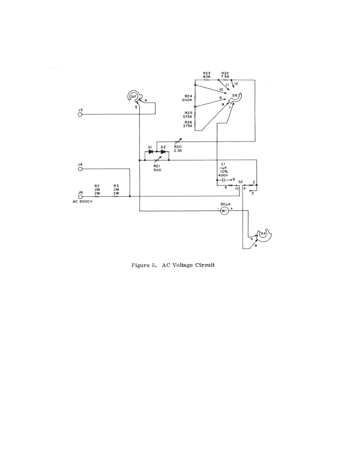
must be placed in series with meter MI so that the meter will provide the proper reading for the selected range scale.
The following contacts of S1E represent the five available voltage ranges: 8 - 1KV/5KV; 9 - 250V; 10 - 50V; 11 - 10V;
12 - 2,5V.
Since the meter deflects only in proportion to the average current level passing through it (and the average value of AC
is zero), the current drawn by the instrument is rectified by a full-wave rectifier circuit consisting of diodes D1 and D2.
The resulting current is a pulsating DC whose average value is proportional to the applied AC voltage. The current-
resistance characteristics of the diodes makes it impractical to try to obtain accurate readings at low currents. Therefore
the instrument is designed to draw about 20 times the current for a measurement of AC voltage as it does for an
equivalent DC voltage measurement. Since the DC sensitivity of the meter is 20,000 ohms/volt, the AC sensitivity is
1000 ohms/volt. Potentiometers R20 and R21 in the rectifier circuit are factory adjusted to provide proper readings with
the RANGE switch in the lowest and highest voltage positions, respectively. The series resistors selected by S1E have
the
13
 Loading...