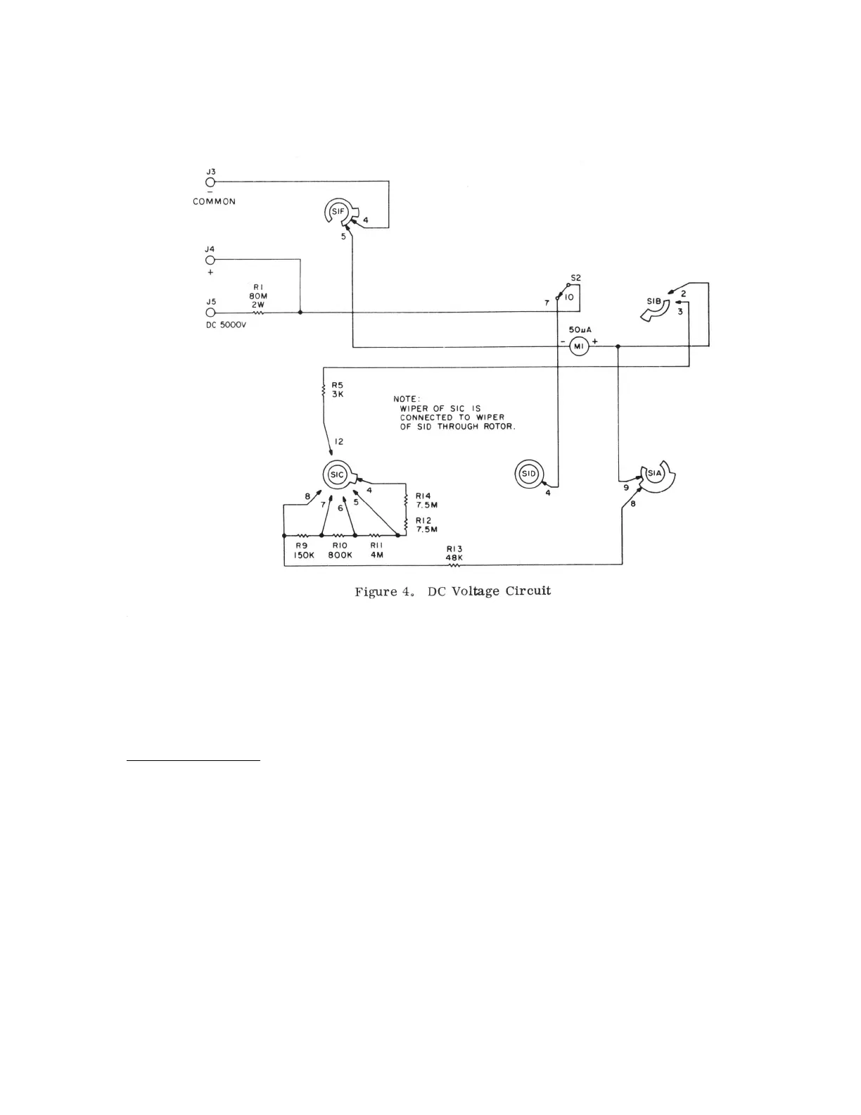
The meter is fully deflected by a current of 50 ua. Therefore the value of the total series resistance for each range
should be equal to the voltage of the range divided by 50 ua (Ohm's Law: R = E/I). For example, for the 50V range, the
series resistance should be 1 Meg. If the series circuit is traced between J3 and J4 (with SI C on contact 6), it will be
found that the resistance will total 1 Meg. (Include 2K for the resistance of the meter.) The same is true for each of the
remaining voltage ranges. When the 5000 volt range is used and the measurement is made between J3 and J5, an
additional 80 Meg resistor is added to the series circuit to provide the required 100 Meg for this range. When actual
voltage measurements are made, any voltage less than the selected range will provide a meter deflection
proportionately less than full scale.
AC Voltage Measurement
Figure 5 shows that portion of the V-20 meter used for AC and output voltage measurements. Contacts 8-10 and 2-4 of
function switch S2 are closed for AC measurements. Here again, jacks J3 and J4 are used to measure all AC voltages
except 5KV, in which case J3 and J6 (A.C. 5000 V.) are used. Deck E of RANGE switch S1 is used to select the
resistance that
12
 Loading...