same proportion to each other for the various ranges as the series resistors selected by S1C for the DC voltage circuit,
except that the AC series resistors are 1/20 the value of the DC resistors.
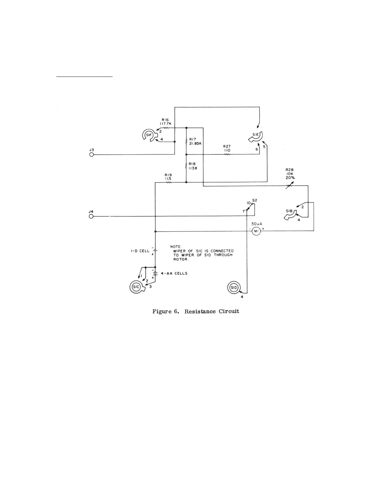
Resistance Measurement
Figure 6 shows that portion of the V-20 meter circuit used for resistance measurements. With the unit used as an
ohmmeter, function switch S2 is in the DC-OHMS position and contacts 7-10 are closed. Resistance measurements are
made between jacks J3 and J4.
The voltage used for the resistance measurements is selected by deck C of RANGE switch S1. The R x 1 and R x 100
ranges use 1.5 volts through contacts 1 and 2 of SIC and contact 4 of SID (wipers of SIC and SID are connected
together); while the R x 10K range uses an additional 6 voIts (contact 3 of SIC). Meter M1 is located in one leg of a
parallel resistance network consisting of resistors R16, R17, R18, H19, and R27. Decks E and F of S1 are used to select
the proper combinations of these resistors for each
14
 Loading...