of the selected ranges. Potentiometer R28 is used to compensate for variations in the battery voltages, thus allowing the
meter to be zeroed for each range.
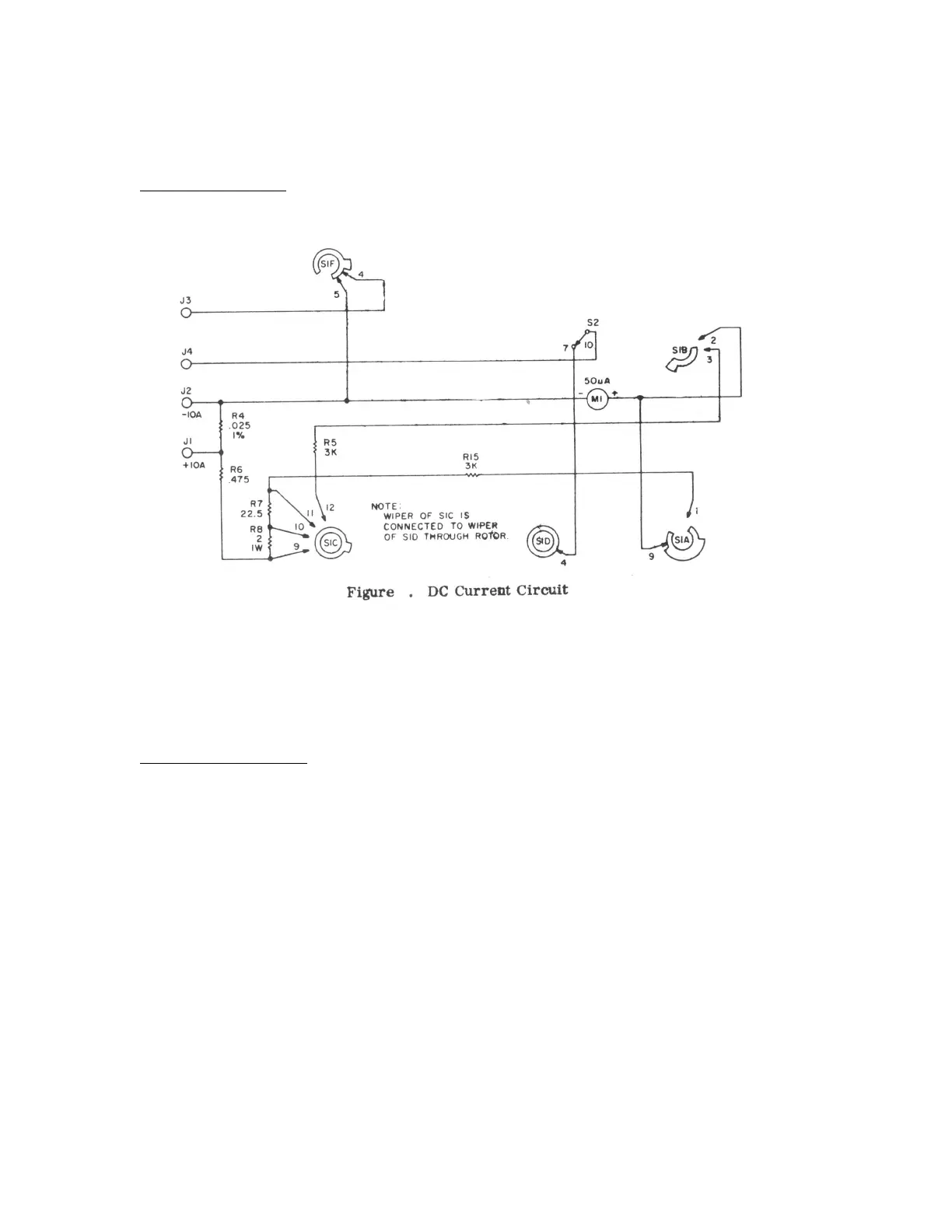
DC Current Measurement
Figure 7 shows that portion of the V- 20 meter circuit used for DC current measurements. In this mode, function switch
S2 is in the DC-OHMS position; and contacts 7-10 are closed. Jacks J3 and J4 are used for all current ranges except the
10 AMP range, in which case jacks J1 and J2 are used.
As in the resistance measurement circuit, meter MI is located in one leg of a parallel resistance network. The
combination of resistors is selected by decks A, B, and C of RANGE switch SI. The higher the current range selected,
the less resistance is placed in parallel With the circuit containing MI, thereby shunting most of the current away from
the meter. However, in the 50 ua range position, there is no shunt leg and all current is passed through the meter (50 ua
is required for full-scale deflection). In the 10 AMP range (when jacks J1 and J2 are used), the shunt circuit consists
only of .025 ohm resistor R4. Jacks J1 and J2 are used in the 10 AMP range to reduce the number of switch contacts
through which high currents must pass.
Output Voltage Measurement
The output voltage measurement circuit (figure 5) description is the same as that listed in the preceding AC section,
except that contacts 9-10 and 3-4 of function switch S2 are closed and capacitor C1 is used to block any DC component
present.
15
 Loading...