EME Controller OE5JFL May 2009
Page 4 of 13
Input/Output: For encoder and motor connection the necessary I/O lines
of the controller are provided at a 20pin connector.
P1.0 ... P1.2 : Az encoder, P1.3 : Az PWM
P1.4 ... P1.6 : El encoder, P1.7 : El PWM
P2.4, P2.5 : Az motor clw,ccw P2.6, P2.7 : El motor up,down
P3.2, P3.3, P3.4, P3.5: future applications
You can design your own input/output drivers, or use the interface
board described below.
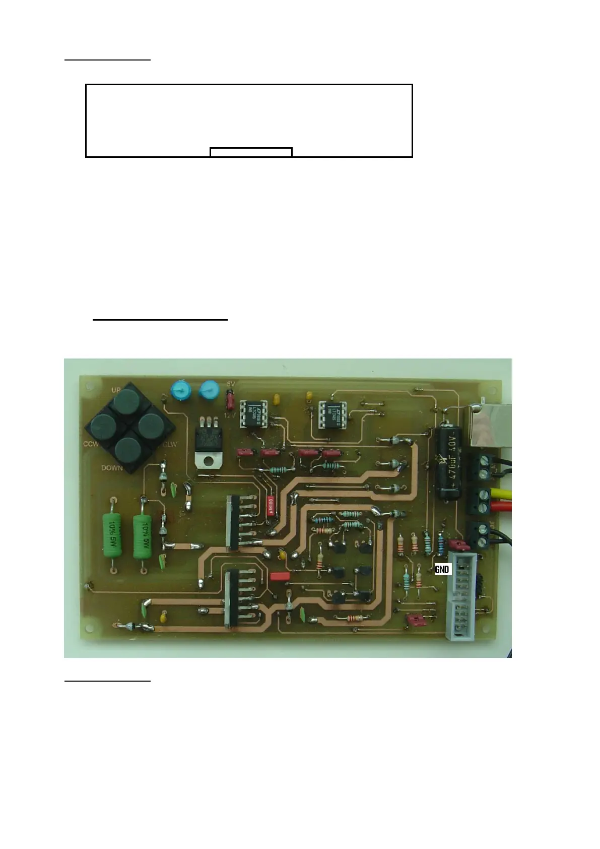
2.Interface board
The interface board is connected to the controller board via the 20pin
connector.
Motor output:
The four controller output signals (P2.4 - P2.7) are activated
(low) in automatic mode. They are amplified by two MOS H-bridges
which can drive DC motors up to 36V/2A. The DC motor inputs must
both be isolated from GND!!
By setting the two jumpers JP6, JP7 a PWM signal for soft start and
slowing down is activated.
If you want to move the antenna in manual mode, switch auto mode
off at the controller, and press the corresponding buttons on the
interface board.
P1.1 P1.3 P1.5 P1.7 P2.5 P2.7 P3.3 P3.5 GND GND
o o o o o o o o o o
P1.0 P1.2 P1.4 P1.6 P2.4 P2.6 P3.2 P3.4 +5V +12V
o o o o o o o o o o