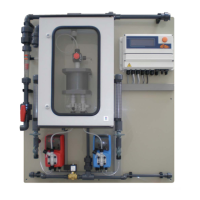
Chlorine Dioxide Generator LOTUS D
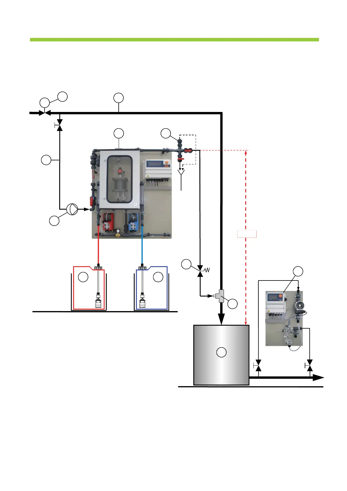
4.5.3 Installation example C
• The reactor outlet valve (9) of the LOTUS system is located beneath the point of injection (34).
• Operation mode: “Proportional”
9 Reactor outlet valve 30 Main water supply
11 Flushing unit with vacuum relieve valve 31 Water meter (frequency or analog signal)
12 Acid tank in safety tub 32 Bypass line
14 Chlorite tank in safety tub 33 Bypass pump
34 Point of Injection (immersion pipe)
35 Delay tank
36 Back pressure valve
40 ClO
2
– Measuring unit type PA-LDCLO2+CP
FIC
12 14
40
35
33
32
11
34
9
30
31
h < 0
36
Fig. 4.3
 Loading...