EasyManua.ls Logo

Emerson Network Power M221S - User Manual

Default Icon
20 pages
Print Icon
To Next Page IconTo Next Page
Loading...
LCU+ Series Controller
User Manual
Version
V1.0
Revision date
March 30, 2010
BOM
31011833
Emerson Network Power provides customers with technical support. Users may contact the nearest
Emerson local sales office or service center.
Copyright © 2010 by Emerson Network Power Co., Ltd.
All rights reserved. The contents in this document are subject to change without notice.
Emerson Network Power Co., Ltd.
Address: No.1 Kefa Rd., Science & Industry Park, Nanshan District 518057, Shenzhen China
Homepage: www.emersonnetworkpower.com.cn
E-mail: support@emersonnetwork.com.cn
Question and Answer IconNeed help?

Do you have a question about the Emerson Network Power M221S and is the answer not in the manual?

Summary

Safety Instructions

Authorization

Defines user roles and responsibilities for equipment handling and maintenance.

Basic Guidelines

Provides general safety recommendations for working with electrical equipment and maintaining a safe environment.

Thunderstorms

Advises on safety precautions related to electrical installations during thunderstorms due to strong electric fields.

Chapter 1 Introduction

Overview

Introduces the LCU+ controller, its functions, and general capabilities.

Technical Specifications

Details the operating conditions, EMC requirements, and mechanical data of the LCU+ controller.

Main Functions

Outlines the primary measurement, display, communication, alarm, and battery management functions of the LCU+.

Hardware Interfaces

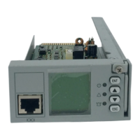
Describes the physical connections and ports available on the LCU+ controller.

Chapter 2 Installation, Replacement And Power-On

Installation and Replacement

Provides step-by-step instructions for removing and installing the LCU+ controller safely.

Initial Startup and Configuration

Guides users through the initial power-on, language selection, and system initialization process.

Chapter 3 Operation

Front Panel Controls and Indicators

Details the physical controls, buttons, and status LEDs on the LCU+ controller's front panel.

Indicator and Control Functions

Explains the behavior of status LEDs and the function of each control button on the panel.

LCD Menu Navigation

Outlines the structure of the LCD menu, including main menus and submenus for operation.

System Status and Settings Access

Describes how to view system status, active alarms, rectifiers, and access the controller's configuration settings.

Overview

The LCU+ Series Controller is a next-generation DC power controller developed by Emerson Network Power, designed for power supply management with a user-friendly and easy-to-use interface. It is available in four models: M221S, M222S, M223S, and M224S.

Function Description

The LCU+ controller provides comprehensive power supply management, monitoring, and control functions for DC power systems. Its main functions include:

  • Measurement Functions:

    • Analog Value Measurement: Measures battery current (differential voltage signal of battery shunt: -100mV to 100mV, error < ±1% of full measurement range), bus voltage (-48V System: 10Vdc to 65Vdc; +24V System: -10Vdc to -30Vdc, ±0.1V absolute value 19V to 60V), temperature (233uA to 373uA, -40°C to 100°C, ±2°C sensor error not considered), and battery string voltage (-48V System: 10Vdc to 65Vdc; +24V System: -10Vdc to -30Vdc, ±0.2V absolute value 19V to 60V). The applicable scope of measurement resolution is 15°C to 30°C.
    • Digital Value Measurement: Monitors load fuse status (2 inputs, 15V to 60V fault, 0 to 1V normal), battery fuse status (4 inputs, <400mV to -50mV normal, >400mV to +50mV fault), DI for status of bi-stable contactor (1 input, 15V to 60V open, 0V to 1V close), DI for auxiliary contact of SPD (1 input), and extended user DI (4 inputs, requiring an expansion board). Load fuse status and battery fuse status input circuits can be reconfigured as battery fuse status, load fuse status, or battery mid-voltage input circuits.
    • Digital Output: Provides 8 extended user DO outputs (configurable, requiring an expansion board), with a contact capacity of 1A / 30Vdc or 125Vac.
    • Power Output: Offers 5VDC, 300mA for external interface board and 10V to 12V, 10mA for temperature sensor.
    • LVD Drive: Features two internal LVD drive outputs capable of driving two bi-stable or mono-stable contactors. Bi-stable contactors support 2A maximum drive current with a pulse width of 500ms to 1s. Mono-stable contactors support 3A maximum starting current and 1A maximum holding current.
  • Display and Indicating Functions:

    • Equipped with a green LED for normal operating status, a yellow LED for observation alarms, and a red LED for major and critical alarms. It also provides a drive output for an alarm LED on the system cabinet.
    • The LCD (128 x 128 for M221S, M222S, M223S; No LCD for M224S) displays AC parameters, DC parameters, rectifier and battery parameters, operating status, alarm status, settings, and control parameters.
  • Communication Functions:

    • Communicates with a host computer via RS232, Modem, and Ethernet (WEB and SNMP).
    • Communicates with rectifiers in CAN-bus mode.
    • Models M221S and M223S support RS232 and Ethernet. Models M222S and M224S support RS232 only.
    • Protocols supported include HTTP and SNMP for M221S and M223S, and YDN23 for all models.
  • Alarm Functions:

    • Automatically generates and reports alarms to a higher-level controller.
    • Records history alarms for user query.
    • Alarm contents include communication failure, SPD fault, DC over/under voltage, load disconnection, battery disconnection, BLVD, battery/ambient temperature abnormal, and rectifier alarm.
    • Four alarm categories: Critical Alarm (CA), Major Alarm (MA), Observation Alarm (OA), and None.
    • Users can set the alarm category for each alarm and block outgoing alarms from reporting to a remote computer or affecting relays. Blocked outgoing alarms generate an 'Outgoing Alarms Blocked' alarm.
    • Alarm levels for temperature sensor disconnected/failure alarms and corresponding relay outputs are fixed to the high temperature alarm setting.
    • Analog alarms with two identical thresholds will only display the first level alarm.
    • Audible alarms can be enabled ('Open') or disabled ('Close') with configurable durations (3min, 10min, 1h, 4h).
    • Alarms can be blocked ('Y' or 'N').
    • Specific alarms (History, ECOFail, Maintain, ShortTest, TestFail, Rect Lost, Rect Commb, Rect Not respond) can be cleared.
  • Battery Management Functions:

    • Battery Test: Checks battery condition by discharging and monitoring battery voltage and current. Reduces rectifier output to a predefined value, allowing the battery to supply the load. Results are saved in a battery test log. Supports full load current test and stable current test. Can be programmed for manual or cyclic start.
    • Battery Boost Charge: Raises system voltage to recharge discharged batteries quicker and equalize differences between battery blocks/cells. Can be programmed for automatic start after Commercial AC Fault (triggered by low battery capacity or high charging current), manual start, or cyclic start.
    • Temperature Compensated Battery Charge: Automatically adjusts system voltage based on battery ambient temperature to extend battery life. System voltage decreases with increasing temperature and increases with decreasing temperature.
    • Battery Current Limitation: Limits current to batteries by adjusting rectifier current limit. Issues a Battery Over Current alarm if the battery current exceeds the alarm setting.
    • Battery Prediction: Calculates remaining capacity and time of the battery during charging or discharging.
  • Low Voltage Disconnect (LVD):

    • Disconnects the load or battery in case of undervoltage or after a predefined time following a Commercial AC Fault to prevent deep discharge and permanent battery damage.
    • Manages up to two internal LVD drive outputs. Disconnection levels for each LVD can be set individually, with one common reconnection level.
    • LVD disconnection level for load contactor should be higher than for the battery contactor.
    • LVD2 (internal) is suggested for battery disconnection to manage large current differences upon AC return.
    • LVD1 and LVD2 can be individually disabled.
    • LVDs reconnect when Commercial AC Fault alarm is inactive and system voltage is above the reconnection level.
    • An LVD alarm is issued upon automatic or manual LVD activation. An LVD Detection Fault alarm is issued if auxiliary input status does not match LVD operation.

Important Technical Specifications

  • Dimensions: 202 × 86.8 × 42 mm (excluding golden finger), 211.5 × 86.6 × 42 mm (including golden finger).
  • Weight: <1kg.
  • Input Voltage: 19V to 60V.
  • Operating Temperature Range (ambient): -10°C to +55°C (LCD display may be difficult to read above 50°C or below -10°C, contrast adjustment may be needed).
  • Storage Temperature: -40°C to +75°C.
  • Relative Humidity: ≤ 90%RH.
  • Elevation: ≤ 3000m.
  • EMC Requirements:
    • EMI: Radiated Emission (EN55022 Class B), Conducted Emission (EN55022 Class B).
    • EMS: Immunity to ESD (IEC61000-4-2, 8kV contact, 15kV air discharge), Immunity to Radiated Magnetic Field (IEC61000-4-3, 10V/m, 80MHz-1GHz, 1.4-2GHz), Immunity to EFT (IEC61000-4-4, 2kV DC Power Input, 1kV Communication Port), Immunity to Surge (IEC61000-4-5, 800V Common Mode DC Power, 500V Differential Mode, 1kV Signal Port), Immunity to Conducted Magnetic Field (IEC61000-4-6, 10Vrms).
  • RoHS Compliance: Complies with RoHS R6 standard.
  • Safety Requirement: CE, UL certified by third party.
  • Protective Level: IP20.

Usage Features

  • Hot Swappable: The controller can be removed and installed while the system is operating.
  • Intuitive Interface: User-friendly and easy-to-use interface with an LCD display (for models M221S, M222S, M223S) and local controls (ENT, Up, Down, ESC keys).
  • Multi-level Menu Structure: Organized LCD menu tree for status, settings, manual controls, ECO functions, and quick settings.
  • Password Protection: Access to the Setting menu requires a password, with three levels (operator1, operator2, administrator) for different access rights.
  • Language Selection: Supports English and local languages for LCD display.
  • System Configuration: Allows configuration of rectifier parameters (position, HVSD, default voltage, walk-in function, current limiting), AC parameters (over/under voltage, phase failure), DC parameters (over/under voltage, ambient high/low temperature), and controller parameters (language, time zone, date, time, system type, download mode, password reset).
  • Remote Access: Supports WEB and SNMP for remote monitoring and control.
  • Bootloader Interface: Provides WEB and Serial Bootloader interfaces for firmware updates and maintenance.

Maintenance Features

  • Installation/Replacement Procedure: Detailed steps for safe removal and installation, including loosening captive fasteners, sliding the controller, and securing it.
  • Pre- and Post-Steps: Guidelines for managing external alarms and ensuring proper grounding during maintenance.
  • Controller Initialization: Automatic initialization routine upon power-on, including language selection and system type configuration.
  • System Status Check: Indicators (green, yellow, red LEDs) provide immediate visual feedback on system status and alarms.
  • Alarm History: Records and allows querying of historical alarms for troubleshooting.
  • Password Reset: Administrator can reset passwords.
  • Parameter Reset: Operator2 can reset parameters to default.
  • Download Mode: Supports serial port download mode for updates.
  • Safety Instructions: Emphasizes authorization levels (User/Operator, Trained User/Operator, Installer), basic guidelines (contact site manager, keep area clean, protect equipment, never work alone, inform personnel upon completion), and thunderstorm precautions (avoid electrical installations, ensure proper earthing).

Emerson Network Power M221S Specifications

General IconGeneral
BrandEmerson Network Power
ModelM221S
CategoryController
LanguageEnglish

Related product manuals