10 Chapter 2 Installation Instruction
NetSure 701 A41, NetSure 501 A41, NetSure 501 A91 Subrack Power system User Manual
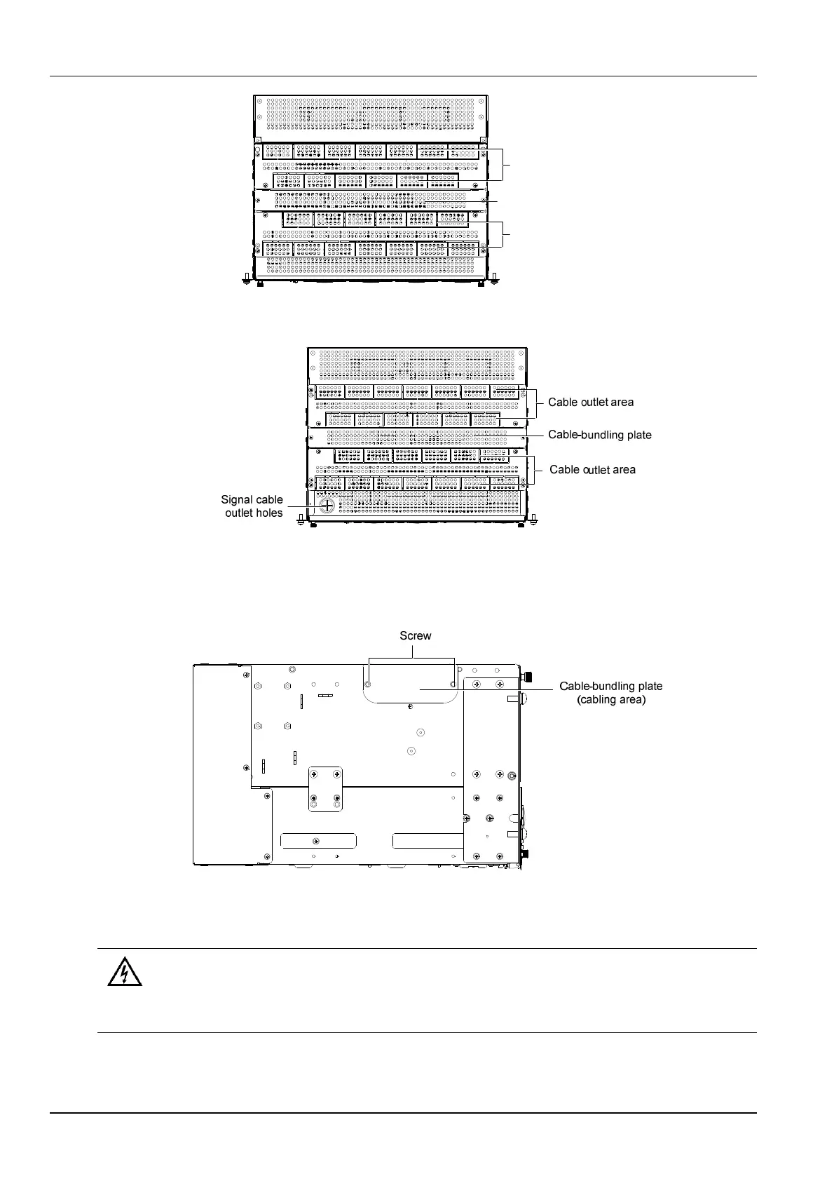
Cable outlet area
Cable-bundling plate
Cable outlet area
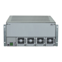
Figure 2-9 Cable entry Illustration of the DU unit
The MFU unit cabling is shown in 2-10.
Figure 2-10 Cable entry Illustration of the MFU unit
Cabling from side of the power system
Use a cross head screwdriver to remove two screws which fix the cabling panel at side of cabling area, then the cable
can be led out from the cabling area, as shown in Figure 2-11.
出线板
(出线空间
螺钉
Figure 2-11 Side cable cabling Illustration
2.4.2 Connecting AC Input Cables
Danger
1. Switch off all MCBs before the electrical connection.
2. Only the qualified personnel can do the mains cable connection.
Take the NetSure 701 A41 power supply system as an example, the position of the terminals are shown in
Figure 2-12.
 Loading...