EasyManua.ls Logo

Emerson 16E09-101 - User Manual

Emerson 16E09-101
16 pages
Print Icon
To Next Page IconTo Next Page
Loading...
CONTENTS
Basic Description ........................................................ 1
Precautions ................................................................. 1
Installation ................................................................... 2
Wiring .......................................................................... 3
User Menu .................................................................. 4
Operation .................................................................... 5
Specifications .............................................................. 7
Troubleshooting ........................................................... 8
www.white-rodgers.com
www.emerson.com
PRECAUTIONS
16E09-101
Universal Electronic Temperature Control
PART NO. 37-6857G
Replaces 37-6857F
1016
INSTALLATION AND
OPERATION INSTRUCTIONS
DESCRIPTION
The 16E09-101 is a single stage electronic temperature con-
trol, with a Nema 1 rated enclosure, and can be used for most
applications within the temperature control range of -40° to
220°F, (-40° to 104°C). The control has an SPDT (Single Pole
Double Throw) output load relay.
The control has user options to control differential, anti-short
cycle delay, set back, offset, alarms and more. It includes an
NTC (Negative Temperature Coefficient) thermistor tempera-
ture sensor, and can be used with certain other NTC or PTC
(Positive Temperature Coefficient) thermistors that meet the
specified resistance vs. temperature specifications. See the
tables on page 7.
The control can fit many applications, which range from
refrigeration to heating due to the wide temperature range of
the control stated above. Typical applications include walk-
in freezers, beverage coolers, supermarket display cases
for flowers, produce, meats, convenience store refrigerated
cases, food warmers, boiler control, and certain industrial
applications.
Save these instructions for future use!
WARNING
!
16E09-101 Optional Accessories / Service Items:
Immerson Well .................................................... F89-0286
Replacement 7.5' NTC Remote Sensor .............. F136-0114
Well Heat Transfer Compound ............................. F145-0163
Failure to read and follow all instructions carefully before
installing or operating this control could cause personal
injury and/or property damage.
To prevent electrical shock, personal injury and/or
equipment damage, disconnect electric power to system
at main fuse or circuit breaker box prior to installation
or service.
To prevent scald injury, do not use this control to
heat water for bathing, washing, hot tub or similar
applications.
Where failure of this control may result in personal
injury and/or property damage, additional alarms or limit
controls must be installed.
This control is a temperature control and is not to be
used as a temperature limit control.
Question and Answer IconNeed help?

Do you have a question about the Emerson 16E09-101 and is the answer not in the manual?

Summary

DESCRIPTION

PRECAUTIONS

INSTALLATION

WIRING

Power Stealing

Explanation of electronic design that eliminates the need for a neutral line to power the control.

USER MENU

USER MENU OPERATION SETTINGS

Explains how user menu settings determine control operation and default factory settings.

OPERATION

COOL;REFRIGERATION

Instructions for using the control as a cooling system, including setpoint and differential settings.

HEAT

Instructions for using the control as a heating system, including setpoint and differential settings.

Lock Panel Operation

Instructions for locking and unlocking the control's keypad to prevent tampering.

Binary Input and Set Back

Configuring binary input for set back and understanding set back temperature changes.

Alarm System and Configuration

Details on alarm relay, conditions, power stealing, and using multiple sensors.

SPECIFICATIONS

Temperature Probes: NTC and PTC

Specifications and resistance tables for NTC and PTC temperature sensors, including cable length and extension limits.

TROUBLESHOOTING

Display and Power Issues

Troubleshooting common problems with the LCD display, back-light, and unit power-on.

Operational and Setting Errors

Resolving issues with temperature differential, setpoint changes, and alarm sound causes.

Power Loss and Alarm Faults

Addressing power loss to the control and troubleshooting unknown alarm sounds.

Overview

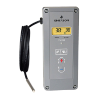
The 16E09-101 is a single-stage electronic temperature control designed for a wide range of applications, from refrigeration to heating. It comes in a Nema 1 rated enclosure and operates within a temperature control range of -40° to 220°F (-40° to 104°C). The control features an SPDT (Single Pole Double Throw) output load relay, allowing it to manage various electrical loads.

Function Description:

The core function of the 16E09-101 is to maintain a desired temperature by controlling an external load. Users can set a specific temperature setpoint and differential, which determines the temperature range within which the control operates. The control can be configured for either "Cut In" or "Cut Out" setpoint modes. In "Cut In" mode, the load is turned on when the temperature reaches the setpoint and off when it reaches the setpoint plus the differential (for cooling) or minus the differential (for heating). In "Cut Out" mode, the load is turned off at the setpoint and on at the setpoint plus the differential (for cooling) or minus the differential (for heating).

The device includes a comprehensive user menu accessible by pressing and holding the MENU button for 5 seconds. This menu allows users to customize various settings, including:

  • Temperature Scale (CF): Selects between Fahrenheit (°F) and Celsius (°C) display.
  • Differential (dFF): Adjusts the temperature difference between the cut-in and cut-out points, ranging from 1 to 30 degrees.
  • Set Point Mode (SP): Determines whether the setpoint is the "Cut In" or "Cut Out" temperature.
  • Sensor Operation Failure (SOF): Configures the relay's behavior in case of a sensor failure. For cooling, users can choose to keep the load contacts closed (default) or open. For heating, sensor failure always results in the relay contacts opening.
  • Display Light (dL): Toggles the LCD display backlight between Off (illuminates for 10 seconds after a button press) and On (continuously illuminated).
  • Anti Short-Cycle Delay (ASd): Sets a minimum time (in minutes) that the load contacts remain open after a cycle before closing again, protecting equipment like compressors from short cycling. This delay can be set from 0 (disabled) to 12 minutes.
  • Lock Front Panel Keypad (LP): Locks the keypad to prevent unauthorized changes to settings.
  • Ambient Temperature Offset (OFS): Allows for calibration of the displayed temperature to compensate for installation or mounting factors, with an adjustment range from -4 to +4 degrees.
  • Binary Input (bln): Enables an external binary input (switch or relay) to trigger a temperature setback.
  • Set Back (Sb): Defines the number of degrees the setpoint temperature will change when the binary input signal is received, ranging from 0 to 50 degrees.
  • Alarm (AL): Configures the time delay (in minutes) before a Temperature Out of Range alarm output is sent, from 0 (disabled) to 99 minutes.

Important Technical Specifications:

  • Load Output Relay Ratings (Maximum):
    • 120VAC: 16A Full Load, 96A Locked Rotor, 16A Non-Inductive, 1 hp.
    • 208VAC: 9.2A Full Load, 55.2A Locked Rotor, 16A Non-Inductive, 1 hp.
    • 240VAC: 8A Full Load, 48A Locked Rotor, 16A Non-Inductive, 1 hp.
    • 24 VAC: 100 VA, 30 VAC Max (Class 2).
    • Pilot Duty: 125 VA, 24 to 240 VAC.
    • Minimum Load Rating: 1 Amp @ 24 VAC.
  • Alarm Relay Ratings (Maximum): N.O. contact: 1 Amp, 5 to 24 V, AC or DC.
  • Operating Ambient Ratings (Control Enclosure): -29°F to 140°F (-34° to 60°C).
  • Storage Shipping Ambient Ratings: -40°F to 185°F (-40° to 85°C).
  • Operating Humidity: 0 to 95% Relative Humidity, Non-Condensing.
  • Maximum Dew Point: 85°F (29°C).
  • Temperature Set-Point Range: -40° to 220°F (-40° to 104°C).
  • Differential Range: 1 to 30 (Degrees F or Degrees C).
  • Case: NEMA 1 Enclosure, Flammability Rating: UL94VO.
  • Temperature Probes: The control is shipped with an NTC (Negative Temperature Coefficient) thermistor with a 7.5-foot cable. Cable length can be extended up to 400 feet using 22 AWG or larger diameter wire. The control can also be connected to existing PTC (Positive Temperature Coefficient) thermistors, provided they meet specified resistance vs. temperature tables. PTC sensor wiring should not exceed 50 feet and use 18 AWG or larger diameter wire.

Usage Features:

The 16E09-101 is highly versatile, suitable for applications such as walk-in freezers, beverage coolers, supermarket display cases (for flowers, produce, meats), convenience store refrigerated cases, food warmers, boiler control, and various industrial applications.

  • Power Stealing Mode: This feature allows the control to be powered directly from the controlled load, eliminating the need for a separate neutral wire connection in some installations. However, it's crucial to note that if the load line is periodically interrupted (e.g., by a defrost timer), the control's display and status LED may turn off, and the alarm feature (if enabled) may trigger false alarms. For systems where continuous power to the control is critical or where the load draws less than 2.5 amps AC, the non-power stealing mode with a neutral wire connection is recommended.
  • Binary Input for Setback: An external switch or relay can be connected to trigger a temperature setback, useful for energy conservation or other operational requirements. The "bln" indicator on the display illuminates when the setback is active.
  • Alarm Functionality: The control includes an alarm relay that activates under specific error conditions: Temperature Out of Range (temperature deviates more than 5° from the setpoint for a defined period), Power Loss (input power failure), and Sensor Operation Failure (open or shorted sensor wiring). The alarm delay for "Temperature Out of Range" is user-configurable.
  • Multiple Sensors: For applications requiring an average temperature reading of an area, up to four identical sensors can be wired in parallel to the control. The control will not operate with two or three sensors.

Maintenance Features:

  • Self-Check: The control periodically performs a self-check, during which the green status indicator LED and display backlight may briefly turn off (up to 15 seconds). This is normal operation and load power is maintained.
  • Factory Default Reset: All settings can be reset to factory defaults by pressing and holding the MENU, +, and - buttons simultaneously for approximately 5 seconds.
  • Keypad Lockout: The keypad can be locked to prevent unauthorized tampering with settings. To unlock, press and hold the MENU button for 5 seconds.
  • Temperature Offset: The "Ambient Temperature Offset" (OFS) setting allows users to fine-tune the displayed temperature to compensate for any inaccuracies caused by mounting or installation factors.
  • Troubleshooting Guide: The manual provides a detailed troubleshooting section for common issues such as display problems, unit not turning on, wide temperature differential, false alarms, and unknown alarm reasons, offering solutions and recommendations for proper wiring and settings adjustments.

Safety Precautions:

The manual emphasizes several critical safety precautions:

  • Always disconnect electrical power before installation or service to prevent electric shock, personal injury, and equipment damage.
  • The control is a temperature control and not a temperature limit control. Additional alarms or limit controls must be installed where failure of this control could result in personal injury or property damage.
  • Do not use this control to heat water for bathing, washing, hot tubs, or similar applications to prevent scald injury.
  • Careful consideration of wiring diagrams and power stealing modes is necessary, especially when using the alarm output in conjunction with devices that may interrupt the load line (e.g., defrost timers), to prevent false alarms.

Emerson 16E09-101 Specifications

General IconGeneral
BrandEmerson
Model16E09-101
CategoryTemperature Controller
LanguageEnglish

Related product manuals