Do you have a question about the Emerson Dixell XR20CX and is the answer not in the manual?
Instructions for manual use, product limitations, and critical safety measures for installation and operation.
Overview of the XR20CX digital thermostat, its features, and applications in refrigeration.
Explanation of how the compressor and defrost functions are controlled.
Detailed explanation of the front panel buttons and their functions.
Description of the status indicated by each LED on the front panel.
Step-by-step guide on how to change parameter values.
Procedure to enter the hidden menu and manage parameters.
Instructions for locking and unlocking the front panel keyboard.
Explanation of continuous cycle operation and the ON/OFF key function.
Settings for differential, min/max setpoints, probe calibration, and continuous cycle.
Configuration for unit of measurement, resolution, and display delay.
Settings for defrost interval, duration, and display during defrost.
Parameters for temperature alarms, delays, and exclusions.
Settings for condenser probe selection and related temperature alarms.
Parameters for digital input polarity and function configuration.
Detailed explanation of various digital input functions like door switch, alarms, and defrost.
List of alarm messages, their causes, and how to recover from them.
Guidelines for mounting the XR20CX controller in a panel.
Instructions for making electrical connections for power and probes.
Procedures for uploading and downloading configurations using the Hot Key.
Information on TTL serial line for monitoring and optional X-REP output.
Detailed technical data including housing, power, inputs, outputs, and environmental ratings.
Wiring diagrams for XR20CX models with compressor outputs.
Table of default values for various parameters and their ranges.
The Dixell XR20CX is a digital thermostat with an off-cycle defrost function, specifically designed for refrigeration applications operating at normal temperatures. This device provides a relay output to control the compressor and features two NTC or PTC probe inputs. The first probe is dedicated to temperature control, while the second, optional probe can be connected to the HOT KEY terminals to signal condenser temperature alarms or display temperature readings. Additionally, a digital input can be configured to function as a third temperature probe.
The XR20CX incorporates a HOT KEY output, enabling connection to a ModBUS-RTU compatible network line, such as Dixell's X-WEB family monitoring units, via an external XJ485-CX module. This feature also allows for convenient programming of the controller using the HOT KEY programming keyboard. The instrument is fully configurable through a set of special parameters, all accessible and programmable via the keyboard.
The primary function of the XR20CX is to regulate the compressor based on temperature readings from the thermostat probe. The compressor starts when the temperature rises and reaches the set point plus a defined differential (Hy). It then turns off when the temperature returns to the set point value. In the event of a fault with the thermostat probe, the compressor's start and stop times are managed by the "COn" and "COF" parameters, respectively.
Defrosting is achieved by simply stopping the compressor. The interval between defrost cycles is controlled by the "IdF" parameter, while the duration of the defrost cycle is managed by the "MdF" parameter.
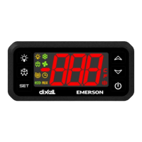
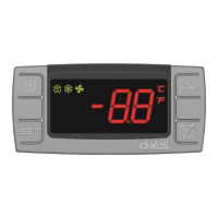
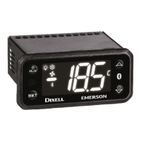
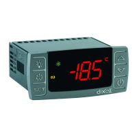
The device includes a front panel with various controls and indicators. The "SET" key is used to display the target set point, select parameters, or confirm operations in programming mode. A dedicated "DEF" key allows for initiating a manual defrost. "UP" and "DOWN" keys are used to view maximum and minimum stored temperatures, browse parameter codes, or adjust displayed values in programming mode. The instrument can be switched off if the "onF" parameter is set to "oFF".
LED indicators provide visual feedback on the device's status. An "ON" LED indicates the compressor is enabled, while a flashing LED signifies an anti-short cycle delay. Other LEDs indicate when defrost is enabled, an alarm is occurring, a continuous cycle is running, or energy saving mode is active. A "°C/°F" LED indicates the measurement unit, and when flashing, it signals the programming phase.
The XR20CX offers several user-friendly features for monitoring and control. Users can easily view the minimum and maximum stored temperatures by pressing and releasing the "DOWN" and "UP" keys, respectively. To reset these recorded temperatures, the "SET" key can be held for more than 3 seconds while the max or min temperature is displayed.
The set point can be viewed by a quick press and release of the "SET" key. To change the set point, the "SET" key is held for more than 2 seconds, and the "UP" or "DOWN" arrows are used to adjust the value. A manual defrost can be initiated by holding the "DEF" key for more than 2 seconds.
The device features a programming mode, accessible by pressing the "SET" and "UP" keys simultaneously for 3 seconds. Within this mode, users can select parameters, view their values, and make adjustments. A "hidden menu" provides access to all instrument parameters, which can be entered by holding the "SET" and "UP" keys for more than 7 seconds after entering the regular programming mode. Parameters can be moved between the hidden menu and the first level (user level) by pressing "SET" and "DOWN" simultaneously.
For security, the keyboard can be locked by holding the "UP" and "DOWN" keys for more than 3 seconds, preventing accidental changes. It can be unlocked by repeating the same action. A continuous cycle can be activated by holding the "DOWN" key for about 3 seconds when defrost is not in progress, allowing the compressor to operate for a duration set by the "CCt" parameter. This cycle can be terminated early by pressing the "DOWN" key again. The ON/OFF function, if enabled ("onF = oFF"), allows the instrument to be switched off by pressing the ON/OFF key, disabling regulation.
The digital input offers versatile configurations, including a door switch input, generic alarm, serious alarm mode, pressure switch input, start defrost function, inversion of action (heating/cooling), and energy saving mode. The polarity of the digital input can also be configured.
The manual emphasizes several safety precautions crucial for maintenance. Users are advised to check the supply voltage before connecting the instrument and to disconnect all electrical connections before any maintenance work. The instrument should not be exposed to water or moisture, and sudden temperature changes with high humidity should be avoided to prevent condensation. The probe should be installed in an area inaccessible to the end-user, and the instrument should not be opened. In case of failure or faulty operation, the instrument should be returned to the distributor or Dixell S.r.l. with a detailed description of the fault.
It is important to consider the maximum current applicable to each relay and to ensure that wires for probes, loads, and the power supply are separated and kept away from each other to prevent crossing or intertwining. For industrial environments, the use of mains filters (e.g., Dixell's FT1) in parallel with inductive loads is recommended.
The device supports programming via a "Hot Key" for easy configuration and maintenance. A programmed "Hot Key" can be used to upload parameters from one controller or download parameters to multiple controllers, simplifying setup and ensuring consistent configurations across devices. This feature is particularly useful for technicians managing multiple units. The instrument provides alarm signals for various conditions, including room probe failure, third/fourth probe failure, maximum/minimum temperature alarms, condenser high/low temperature alarms, door open alarms, external alarms, and pressure switch alarms. These alarms aid in diagnosing issues and performing timely maintenance. Probe alarms automatically stop once the probe returns to normal operation, while temperature alarms recover when the temperature returns to normal values. External and serious alarms recover when the digital input is disabled, and pressure switch alarms require the instrument to be switched off and on to restart normal regulation.
| Output Type | Relay |
|---|---|
| Power Consumption | 3VA max |
| Operating Temperature | 0 to 60°C |
| Resolution | 0.1°C |
| Frontal Protection | IP65 |
| Dimensions | 74 x 32 x 60 mm |
| Type | Controller |
| Input Type | NTC |
| Display | 3-digit LED |
| Power Supply | 24V AC/DC ±10% |
| Accuracy (ambient temp. 25°C) | ±1°C |
| Relative Humidity | 20% to 90% non-condensing |